Self-powered device for shipborne positioning and tracking system

A tracking system, ship-borne positioning technology, applied in electromechanical devices, electrical components, generators/motors, etc., to achieve the effect of effective frequency bandwidth, strong environmental adaptability, and high reliability

Pending Publication Date: 2017-11-17
ZHEJIANG NORMAL UNIVERSITY
View PDF7 Cites 4 Cited by
  • Summary
  • Abstract
  • Description
  • Claims
  • Application Information

AI Technical Summary

Problems solved by technology

[0003] Aiming at some problems existing in the use and power supply of the existing ship monitoring sys

Method used


Image

  • Self-powered device for shipborne positioning and tracking system
  • Self-powered device for shipborne positioning and tracking system

Examples


Embodiment Construction

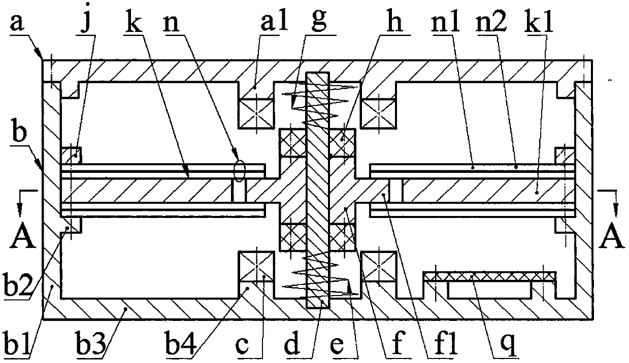
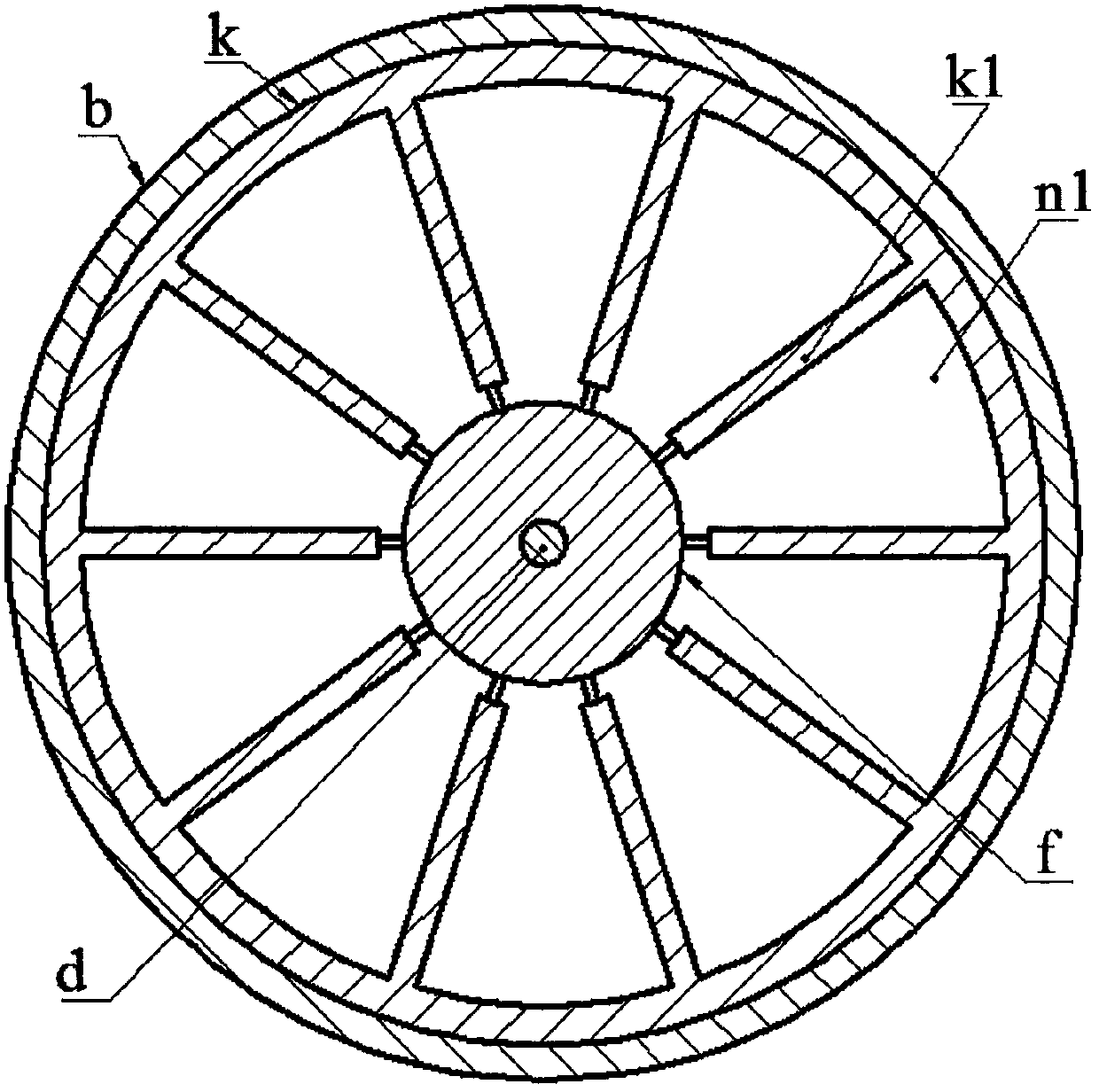
[0009] The upper cover a is installed on the end of the cylinder wall b1 of the shell b through screws, and the cylinder wall b1 is provided with a cylinder wall boss b2; the boss a1 of the upper cover a and the boss b4 of the bottom wall b3 of the shell are both screwed A coil c is installed; both ends of the guide post d are respectively fixed on the upper cover a and the bottom wall b3 of the housing, and the guide post d is sequentially covered with a balance spring e, an inertia block f and a limit spring g, and the balance spring e And the limit spring g is a disc spring, the side of the inertial block f is provided with a wing plate f1, and the upper and lower ends of the inertial block f are installed with a generator h through screws; the upper surface of the generator h above the inertial block f and its adjacent coil The lower surface of c is located on the same plane, the lower surface of the electromagnet f under the inertia block f and the upper surface of its adj...


PUM


Abstract

The invention relates to a self-powered device for a shipborne positioning and tracking system, and belongs to the technical field of ship electronics. An upper cover is arranged at the end portion of the wall of a shell. Bosses on the upper cover and on the bottom wall of the shell are respectively provided with a coil. The two ends of a guide column are fixed on the upper cover and the bottom wall of the shell. The guide column is sequentially sleeved with a balance spring, an inertia block and a limiting spring from bottom to top. The side edge of the inertia block is provided with a wing plate. The upper end and the lower end of the inertia block are provided with power generation magnets. The thickness of the power generation magnets is the same as the thickness of the coils. Two sets of energy transducers are evenly distributed on the boss on the wall of the shell through a pressing ring and a spacer ring. Limiting radial plates are uniformly distributed on the spacer ring. The two sets of energy transducers are symmetrically arranged on the upper side and the lower side of the spacer ring. The limiting radial plates are located between two adjacent energy transducers on the circumference, and the width of the limiting radial plates is larger than the distance between every two adjacent energy transducers. Each energy transducer is formed by bonding a substrate and a piezoelectric film, and the substrate is arranged close to the spacer ring. The substrate and the limiting radial plates are in contact with the wing plate of the inertia block, while no interaction force exists. The energy transducers are in the natural vertical state.

Description

technical field [0001] The invention belongs to the technical field of ship electronic applications, and in particular relates to a self-power supply device for a ship-borne positioning and tracking system. Background technique [0002] The ship positioning and tracking system has been widely used on civil ships, providing a strong technical support for the ship's navigation safety, timely rescue, and lost contact search. However, the existing positioning and tracking systems are all based on engine power supply. Once an accident occurs on the ship and the engine and the entire power system fail, the positioning and tracking system will lose its proper function. In addition, the existing positioning and tracking systems are all external, and cannot work normally when the ship is wrecked and flooded, and the positioning system is easily shut down or destroyed after the ship is hijacked by criminals. Therefore, in order to ensure the safe and reliable operation of the ship po...

Claims


Application Information

Patent Timeline
IPC IPC(8): H02K35/02H02N2/18
CPCH02K35/02H02N2/183
Inventor 蒋永华朱雅娜温建明
Owner ZHEJIANG NORMAL UNIVERSITY
Why Eureka
Try Eureka