
Coffee maker

A coffee machine and coffee technology, applied in beverage preparation devices, home appliances, applications, etc., can solve the problems of low brewing concentration, affecting taste, and high product manufacturing costs

Pending Publication Date: 2017-11-21
金文 +1
View PDF8 Cites 5 Cited by
  • Summary
  • Abstract
  • Description
  • Claims
  • Application Information

AI Technical Summary

Problems solved by technology

[0004] (1) The heat is easily lost, resulting in a low extraction rate of coffee powder (only about 18%) and a low brewing concentration;
[0005] (2) Only rely on the gravity of the coffee powder itself to filter, then, if the filter mesh is designed too densely, it will be difficult to drip and brew, which prolongs the production time of coffee drinks; otherwise, if the filter mesh is designed too sparsely (such as The filter mesh of the current drip coffee machine can only be set to 80-100 mesh at most), and the brewed coffee contains more dregs, which greatly affects the taste
[0006] For the capsule coffee machine, although it solves the above-mentioned technical problems of the drip coffee machine to a certain extent, that is, it can increase the extraction rate of the coffee powder and the purity of the coffee, and the brewing efficiency is also improved, but because of Only special coffee capsules can be used, so the cost of self-made coffee drinks is relatively high. In addition, the structure of the capsule coffee machine is also relatively complicated, and the product manufacturing cost is also high

Method used


Image

  • Coffee maker
  • Coffee maker
  • Coffee maker

Examples


Embodiment 1

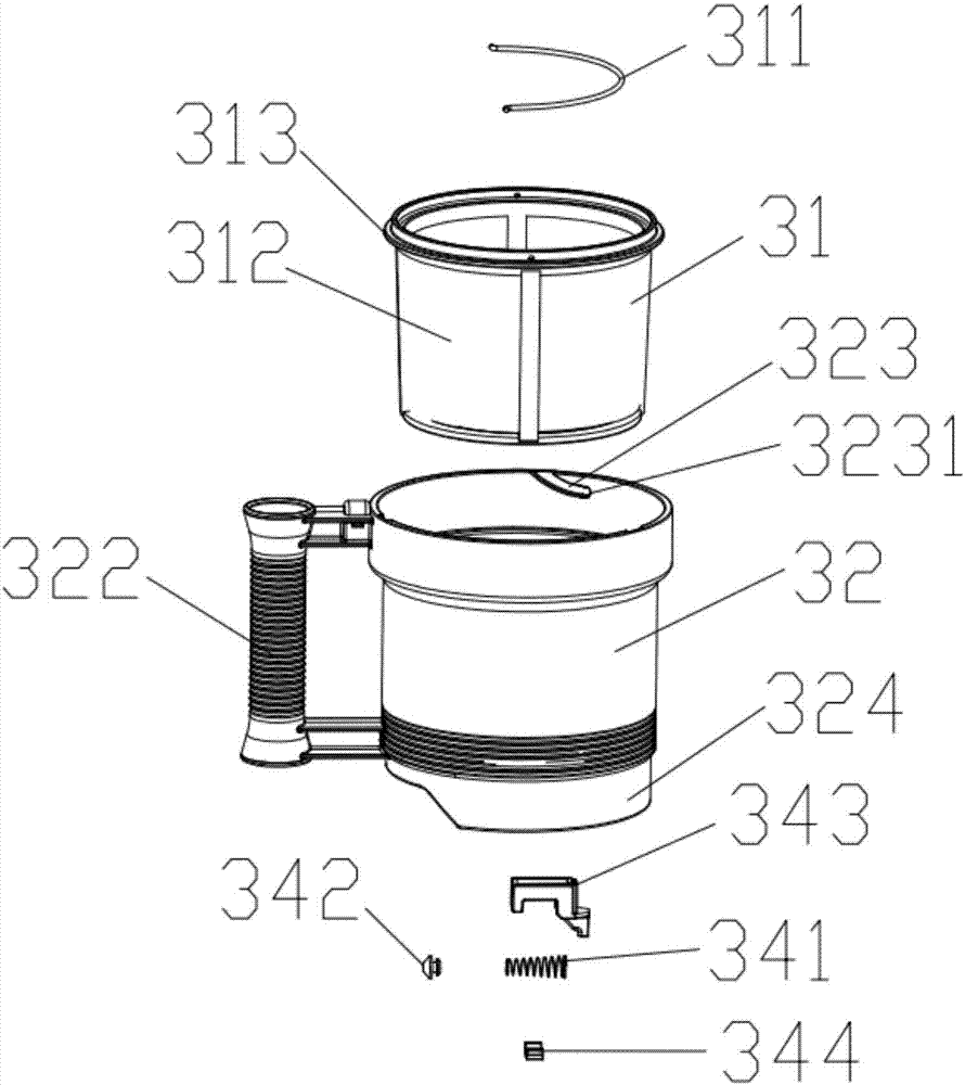
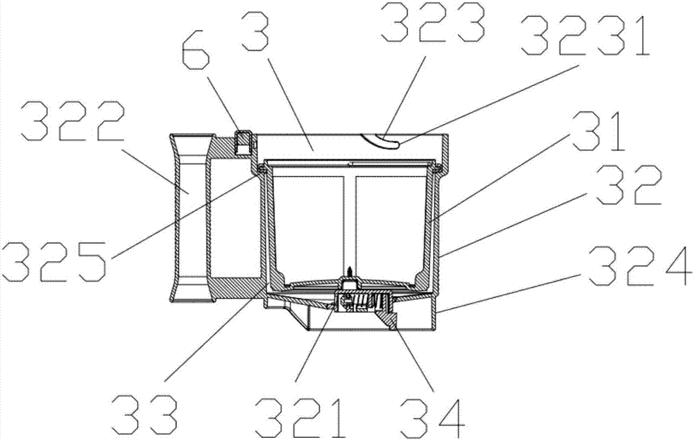
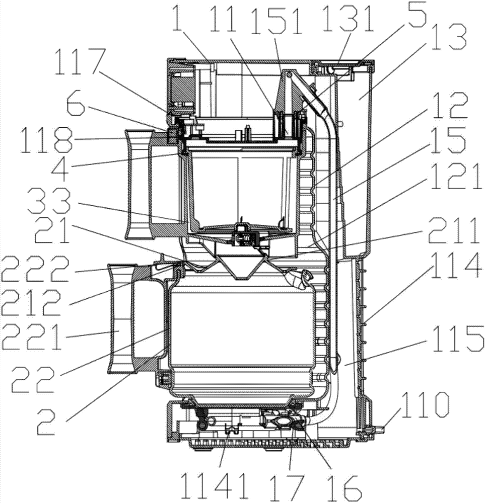
[0114] This embodiment discloses a coffee machine, such as Figure 1~4 , 21, 22, including a main machine 1, a coffee cup 2, and a processing bucket 3, the three are independent of each other, the processing bucket 3 is used for filtering coffee liquid, and the main machine 1 is provided with a first water inlet 11.

[0115] The processing bucket 3 includes an inner bucket 31 and an outer bucket 32 ​​for containing coffee raw materials; There is a first water outlet 321 .

[0116] In this example, if figure 1 As shown, the filter screen 312 is used as the side wall of the inner bucket 31, and it is made of a metal material. It can also be used as the bottom of the inner bucket 31, and can also be made of other materials, such changes all belong to the equivalent protection scope of the present invention.

[0117] When the processing bucket 3 is installed on the main machine 1, the inner bucket 31 fits in the outer bucket 32 ​​and forms a first cavity 33 communicating with t...

Embodiment 2

[0157] This embodiment discloses another coffee machine, which differs in structure from the coffee machine described in Embodiment 1 in that:

[0158] (1) In this embodiment, if Figure 5 As shown, the host 1 is provided with a plurality of lighting indicator lights 7 for prompting that the processing bucket 3 is installed in place and illuminating the inside of the processing bucket 3, and each lighting indicator light 7 is electrically connected with the control circuit board 19; The indicator lights 7 are evenly distributed in the circumferential direction. When the processing bucket 3 is installed on the main machine 1, each lighting indicator light 7 is located above the processing bucket 3 to illuminate the entire transparent inside of the processing bucket 3, so that users can observe the processing bucket 3 at any time. The internal working conditions are more humane.

[0159] (2) In order to provide a more spacious layout space for the circuit that supplies power to...

Embodiment 3

[0163] This embodiment discloses another coffee machine, which differs in structure from the coffee machine described in Embodiment 1 in that:

[0164] In this example, if Figure 6-9 As shown, the processing bucket 3 also includes a bucket cover assembly 35;

[0165] When the processing bucket 3 is installed on the main machine 1, the bucket cover assembly 35 is fastened to the inner bucket 31, and the bucket cover assembly 35 and the inner cavity of the inner bucket 31 form a second cavity 36, and the first water inlet 11 and the second cavity 36 is connected to the water inlet, and the area between the opening of the inner bucket 31 and the opening of the outer bucket 32, and the bonding area between the bucket cover assembly 35 and the inner bucket 31 are all sealed.

[0166] Specifically, in this embodiment, as Figure 6-9As shown, when the processing bucket 3 is installed on the main machine 1, the bonding area between the bucket cover assembly 35 and the inner bucket ...


PUM

PropertyMeasurementUnit
Meshaaaaaaaaaa

Abstract

The invention discloses a coffee maker, which comprises a main machine, a coffee cup and a processing hopper capable of smashing or stirring a coffee raw material and filtering coffee liquid, wherein a first water inlet is formed in the main machine; the processing hopper comprises an inner hopper body and an outer hopper body which are used for accommodating the coffee raw material, a lateral wall of the inner hopper serves as a filter screen, and a first water outlet is formed in the outer hopper; when the processing hopper is installed on the main machine, the inner hopper body is in sleeve fit in the outer hopper body, a first accommodating cavity communicated with the first water outlet is formed between the inner hopper body and the outer hopper body, the first water inlet is communicated with the inner cavity of the inner hopper body, and the first water outlet can be communicated with the inner part of the coffee cup, and an area between the inner hopper body and the main machine and an area between an opening of the inner hopper body and an opening of the outer hopper body are both sealed. According to the coffee maker disclosed by the invention, the whole structure of newly improved to introduce a micropressure principle into the coffee maker; thus, not only can a coffee extracting rate and coffee drink purity be improved based on effectively shortening coffee making time, but also self making cost of coffee is low.

Description

technical field [0001] The invention belongs to the technical field of household appliances, and in particular relates to a coffee machine. Background technique [0002] Coffee is one of the most popular drinks in the world. It can bring pleasure and excitement to people. With the continuous improvement of people's living standards, there is an increasing pursuit of homemade coffee and coffee taste. A coffee machine is a general term for a coffee brewing machine, and it is the best choice for people to make their own coffee drinks. Today, the coffee machines active in the market are mainly drip coffee machines and capsule coffee machines. [0003] However, for the drip coffee machine, there are many defects because it needs to vent holes above the coffee bucket for holding coffee powder so that it can work in a pressure-free state, such as: [0004] (1) The heat is easily lost, resulting in a low extraction rate of coffee powder (only about 18%) and a low brewing concentra...

Claims


Application Information

Patent Timeline
IPC IPC(8): A47J31/30A47J31/06
CPCA47J31/0663A47J31/30
Inventor 金文胡伟卿宙
Owner 金文
Learn More