Plane bending forming clamping device and die with clamping device

A clamping device and plane technology, which is applied in the field of clamping devices for flat bending of copper bars, can solve the problems of difficulty in ensuring the quality of molding, cumbersome installation and disassembly procedures, and poor quality stability of molded parts, achieving simple structure, Guaranteed surface smoothness, easy construction and portability

Pending Publication Date: 2017-11-21
大唐国信滨海海上风力发电有限公司
View PDF10 Cites 2 Cited by
  • Summary
  • Abstract
  • Description
  • Claims
  • Application Information

AI Technical Summary

Problems solved by technology

[0005] The technical problem to be solved by the present invention mainly lies in overcoming the difficulty of forming copper (aluminum) row planar planes with existing copper (aluminum) row bending tools, the low precision of the forming angle, the poor quality stability of the formed parts, and the surface of the formed parts. Scratches and forming quality are difficult to be guaranteed, single application occasions, cumbersome installation and disassembly procedures, etc., to provide a copper (aluminum) row bending with simple structure, convenient installation, and can be obtained according to the requirements of different forming angles The clamping device with high precision angle and less scratches on the surface of the molded parts. The clamping device can be adjusted according to the requirements of different forming angles. , easy to disassemble, etc.

Method used


Image

  • Plane bending forming clamping device and die with clamping device
  • Plane bending forming clamping device and die with clamping device
  • Plane bending forming clamping device and die with clamping device

Examples


Embodiment 1

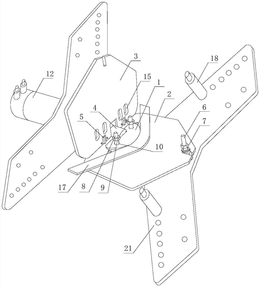
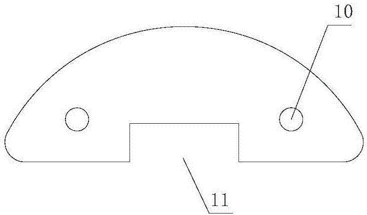
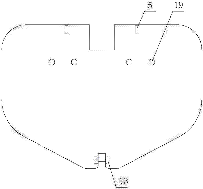
[0054] Such as Figure 1 to Figure 10 As shown, the first choice is to place the clamping device (20) in the hydraulic pipe bender (12), insert the hydraulic rod into the sinking groove of the sleeve head 4, select the appropriate angle forming module 1 according to the raw material specification, and form the mold according to the angle Positioning hole (10) of part 1, fix the angle forming module 1 on the first splint 2, the positioning bolt on the first splint 2 passes through the positioning hole (10) of the angle forming module 1, delineate on the raw material The position of the inflection point is placed flat on the first splint 2, the inflection point is aligned with the center of the angle forming module 1, and the second splint 3 is closed so that the positioning screw 8 passes through the positioning screw 8 holes on the second splint 3, and at the same time Set the positioning screw nut (9) on the positioning screw 8, use the first clamping plate 2 and the second c...

Embodiment 2

[0056] The difference between this embodiment and the above-mentioned first embodiment is that the angle forming module 1 is located on the side away from the connector of the first splint 2, the sleeve 4 is still welded on the first splint 2, and the forming part (17) is against Hold the support (18), the hydraulic pipe bender (12) starts, the hydraulic rod is inserted into the sleeve 4, and the hydraulic rod drives the entire clamp to move forward until the formed part (17) is between the support (18) and the hydraulic pipe bender ( 12) Under the action of plane bending molding.

Embodiment 3

[0058] The difference between this embodiment and the first embodiment above is that there are two locking devices, which are symmetrically arranged on both sides of the first splint 2 .


PUM


Abstract

The invention discloses a plane bending forming clamping device and a die with the clamping device. The plane bending forming clamping device comprises a first clamping plate, a second clamping plate and an angle forming die piece arranged between the first clamping plate and the second clamping plate. The first clamping plate and the second clamping plate are hinged through a connecting piece. The angle forming die piece arranged between the first clamping plate and the second clamping plate is locked through a locking device via the first clamping plate and the second clamping plate. The angle forming die piece is arranged on the side, close to the connecting piece, of the first clamping plate. The angle forming die piece is arranged on the side, close to the connecting piece, of the first clamping plate. The side, away from the connecting piece, of the angle forming die piece is an arc making contact with a formed piece. The plane bending forming clamping device and the die with the clamping device solve a series of problems that an existing copper (aluminum) row bending tool difficultly bends and forms a copper (aluminum) row plane, the forming angle precision is low, an obtained formed piece is poor in quality stability, scratches exist on the surface of the formed piece, the forming quality is hard to guarantee, applicable occasions are single, and mounting and dismounting procedures are complex.

Description

technical field [0001] The invention belongs to the technical field of the copper industry, and in particular relates to a copper (aluminum) row planar bending forming clamping device and a mold with the clamping device. Background technique [0002] Copper (aluminum) bars play the role of transmitting current and connecting electrical equipment in the circuit, and are widely used in electrical equipment, especially complete power distribution devices, especially in the electrical cabinets of substations, many copper bars are used (aluminum) row, due to the special application of copper (aluminum) row, in the process of using copper (aluminum) row for equipment surface laying grounding or hard busbar connection between equipment, it is necessary to carry out copper (aluminum) row after production. Bending to meet the installation requirements, although there are many bending tools for copper (aluminum) rows, most of them can meet the processing accuracy, but the production p...

Claims


Application Information

Patent Timeline
Patent Type & Authority Applications(China)
IPC IPC(8): B21D7/16B21D43/00B21D37/10
CPCB21D7/16B21D37/10B21D43/003
Inventor 范玉鹏郑心勤王敏缪翔张梦超姜浩常亮宋国锋
Owner 大唐国信滨海海上风力发电有限公司
Why Eureka
Try Eureka