Automatic correction device and automatic correction method for component position of placement machine feeder

A component position and feeder technology, which is applied in the direction of assembling printed circuits with electric components, can solve the problems of low precision and achieve the effects of high correction precision, fast identification and processing speed, and cost reduction

Active Publication Date: 2019-02-22
HARBIN INST OF TECH
View PDF5 Cites 0 Cited by
  • Summary
  • Abstract
  • Description
  • Claims
  • Application Information

AI Technical Summary

Problems solved by technology

[0005] The present invention solves the problem of low accuracy of the existing feeder relying on manual correction or mechanical correction of the initial position of the element

Method used


Image

  • Automatic correction device and automatic correction method for component position of placement machine feeder
  • Automatic correction device and automatic correction method for component position of placement machine feeder
  • Automatic correction device and automatic correction method for component position of placement machine feeder

Examples


specific Embodiment approach 1

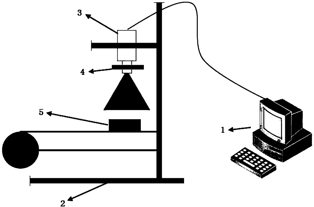
[0071] Specific implementation mode one: combine figure 1 To describe this embodiment,

[0072] An image processing-based device for automatically correcting the position of feeder components of a placement machine, comprising a host computer 1, a correction fixture 2, an industrial camera 3 and an LED light source 4; the host computer 1 is connected to the industrial camera 3; the industrial camera 3 and the feeder The feeder is fixed on the straightening fixture 2, the outlet of the feeder is aligned with the component conveyor belt, the industrial camera 3 is aligned with the outlet of the feeder and in front of the outlet, and the industrial camera 3 is used to collect the components 5 at the outlet of the feeder in real time The position image of the LED light source 4 is an adjustable light source, located at the camera head of the industrial camera 3, and the LED light source 4 is used to adjust the intensity of light in the lighting environment;

[0073] The upper com...

specific Embodiment approach 2

[0074] The control system for automatically correcting the component position of the chip mounter feeder built in the host computer described in this embodiment includes:

[0075] Communication module, used to select the correct serial port to communicate with the mounter feeder;

[0076] The display module is used to display images and prompt information; the display module includes an image display sub-module and an information prompt sub-module; wherein,

[0077] The image display sub-module is used to display the image collected by the camera in the image display window in real time;

[0078] The information prompt sub-module is used to display operation and warning prompt information;

[0079] The operation module is used to control the camera, the collected images, and correction commands and data; the operation module includes a camera control submodule, an image operation submodule, a correction command sending submodule and a data storage submodule; wherein,

[0080...

specific Embodiment approach 3

[0085] The information prompt sub-module described in this embodiment includes:

[0086] An operation information prompt unit is used to display each operation information of the operator in the operation information prompt area in real time;

[0087] The warning information prompting unit is used to prompt the user's attention and misoperation by popping up a warning information dialog box.

[0088] Other system modules and structures are the same as those in the second embodiment.


PUM


Abstract

The invention discloses an automatic surface mounting machine feeder element position correction device and an automatic correction method based on image processing, which relate to the automatic correction devices and methods for the surface mounting machine feeder element position and solve the problems that the existing feeder depends on manual correction or the precision is low when the initial element position is corrected mechanically. The device comprises an upper computer, a correction fixing device, an industrial camera and an LED light source, wherein the upper computer is connected with the industrial camera; the industrial camera is fixed on the correction fixing device for acquiring the position image of an element at the exit of the feeder in real time; the LED light source is located at the camera lens of the industrial camera; and the upper computer is internally provided with an automatic surface mounting machine feeder element position correction control system, the system is used for controlling the industrial camera to acquire an image, the acquired image is displayed on an image display window in real time, and after processing of the element position image and calculation of position information data, a correction command is sent to control a correction action. The device and the method of the invention are used for element position correction.

Description

technical field [0001] The invention relates to an automatic correcting device and method for the component position of a mounter feeder. Background technique [0002] Under the development trend of industrial automation, relying on traditional manual operation can no longer meet the requirements of modern production mode of mass production and complex assembly process. The advanced manual detection technology cannot meet the accuracy requirements at all. The visual inspection technology based on digital image processing technology has gradually replaced the traditional manual inspection technology by relying on the advantages of high precision, high efficiency and low cost, and is widely used in various manufacturing fields. [0003] Because the placement machine feeder needs to correct the initial position of the component to the standard position before leaving the factory and during use, the traditional correction method relies on human eyes to read the image position a...

Claims


Application Information

Patent Timeline
Patent Type & Authority Patents(China)
IPC IPC(8): H05K3/30
CPCH05K3/30
Inventor 高会军郭丰钰孙乙铭于金泳孙昊
Owner HARBIN INST OF TECH
Why Eureka
Try Eureka