
Chip removal device for lathe bed of numerical control machine tool

A CNC machine tool and bed technology, which is applied to metal processing machinery parts, maintenance and safety accessories, metal processing equipment, etc., can solve problems such as low production efficiency, large maintenance funds, and machine tool damage, so as to avoid the reduction of processing efficiency, Novel design and thorough cleaning effect

Inactive Publication Date: 2017-11-21
成都捷科菲友信息技术有限公司
View PDF0 Cites 2 Cited by
  • Summary
  • Abstract
  • Description
  • Claims
  • Application Information

AI Technical Summary

Problems solved by technology

[0003] The bed of the CNC machine tool is the basic support of the entire machine tool, which is generally used to prevent important parts such as guide rails and spindle boxes. The bed of the CNC machine tool is generally equipped with multiple sets of processing grooves. After the parts are processed, a large amount of waste will be generated. It is relatively easy to clean the waste chips on the surface of the machine tool, but it is difficult to remove the waste chips in the processing tank manually. If the waste chips are not cleaned for a long time, the processing efficiency of the machine tool will be seriously affected, resulting in low production efficiency, and in severe cases, the machine tool will be damaged. Requires a lot of money for repairs

Method used


Image

  • Chip removal device for lathe bed of numerical control machine tool
  • Chip removal device for lathe bed of numerical control machine tool

Examples


Embodiment Construction

[0016] The technical solutions in the embodiments of the present invention will be clearly and completely described below in conjunction with the accompanying drawings in the embodiments of the present invention. Obviously, the described embodiments are only some of the embodiments of the present invention, not all of them.

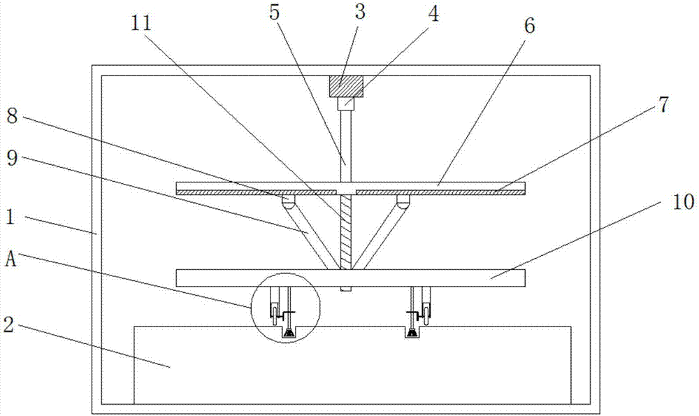
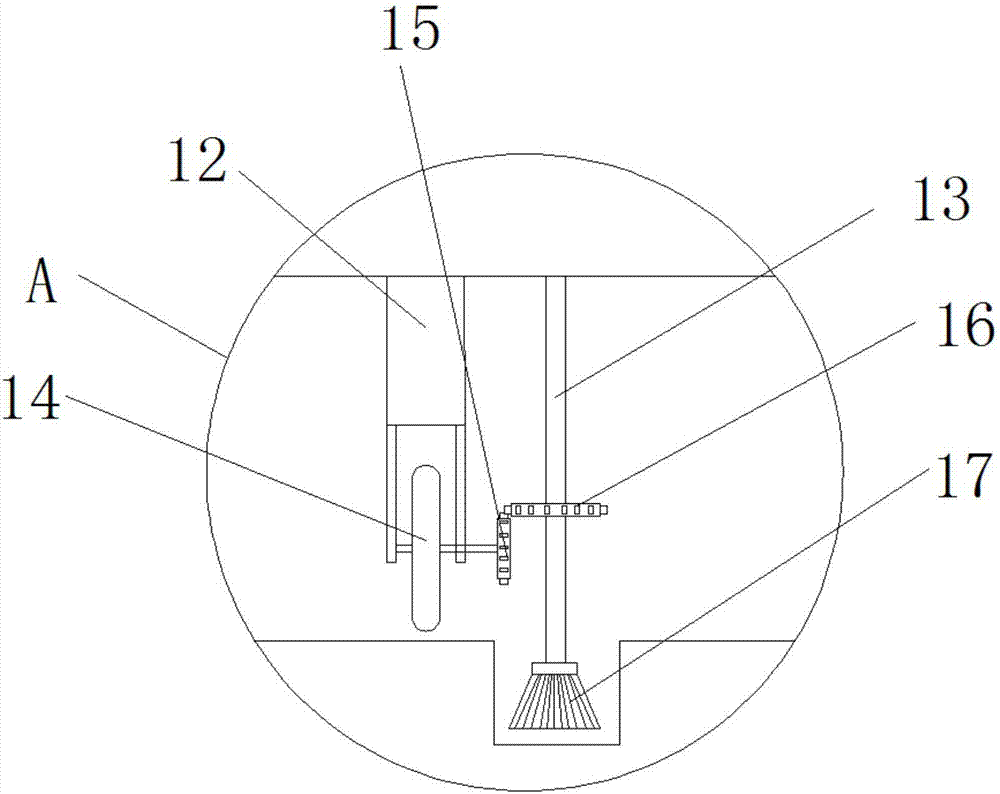
[0017] refer to Figure 1-2 , a chip removal device used on the bed of a numerically controlled machine tool, comprising a machine tool main body 1, a machine bed 2 welded to the bottom of the machine tool main body 1, a track 3 is provided along the width direction at the middle position of the inner wall of the top plate of the machine tool main body 1, and the track 3 is movable and installed There are mobile device 4, mobile device 4, mobile device 4 has mobile wheel and mounting plate, mobile wheel is installed on the mounting plate through bearing, and mobile wheel is movably installed on track 3, mounting plate connects fixed bar 5, mobile device 4 ...


PUM


Abstract

The invention discloses a chip removal device for a lathe bed of a numerical control machine tool. The chip removal device comprises a machine tool body, the lathe bed is welded to the bottom of the machine tool body, a rail is arranged at the position of the middle of an inner wall of the top of the machine tool body along the width direction, a moving unit is movably mounted in the rail, the bottom of the moving unit is connected with one end of a fixing rod, the other end of the fixing rod is connected with a first support plate, sliding chutes are symmetrically arranged in two sides of the lower surface of the first support plate, one slider is movably arranged in each sliding chute, bottoms of the sliders are hinged to one ends of connecting rods, the other ends of the connecting rods are hinged to the upper surface of a second support plate, and a through hole is formed in the middle of the second support plate. By the arrangement, chips in a machining groove of the lathe bed of the numerical control machine tool can be removed automatically, machining of the numerical control machine tool is unaffected, reduction in machining efficiency is avoided, and running of the machine tool is protected to some extent.

Description

technical field [0001] The invention relates to the technical field of numerical control machine tools, in particular to a chip removal device used on the bed of a numerical control machine tool. Background technique [0002] CNC machine tool is the abbreviation of Computer numerical control machine tools, which is an automatic machine tool equipped with a program control system. The control system can logically process programs with control codes or other symbolic instructions, decode them, express them in coded numbers, and input them into the numerical control device through the information carrier. After calculation and processing, various control signals are sent by the numerical control device to control the movement of the machine tool, and the parts are automatically processed according to the shape and size required by the drawing. CNC machine tools solve complex, precise, small-batch, and multi-variety parts processing problems. It is a flexible, high-efficiency a...

Claims


Application Information

Patent Timeline
IPC IPC(8): B23Q11/00
CPCB23Q11/0042
Inventor 不公告发明人
Owner 成都捷科菲友信息技术有限公司
Learn More