Water tank feeding and discharging clamp and method for machining water tank with same

A water tank and material clip technology, applied in metal processing equipment, manufacturing tools, grinding feed motion, etc., can solve the problems of low loading and unloading efficiency and product quality, easy deformation, and weak clamping.

Active Publication Date: 2017-11-21
GUANGDONG LXD ROBOTICS CO LTD
View PDF5 Cites 1 Cited by
  • Summary
  • Abstract
  • Description
  • Claims
  • Application Information

AI Technical Summary

Problems solved by technology

Manual loading and unloading is labor-intensive, prone to bumps, low production efficiency, and high defective rate; if the robot hand directly clamps the water tank for loading and unloading, the position of the water tank clamped by the robot hand is prone to deformation and the clamping is not firm , easy to fall off, and without the aid of clamps, it is difficult for the robot to complete the loading and unloading operation of the water tank at one time. It needs to clamp and adjust the water tank many times, which will cause bumps and scratches on the water tank. This way of loading and unloading Although the problem of high manual labor intensity can be solved, there are still problems of loading and unloading efficiency and low product quality

Method used


Image

  • Water tank feeding and discharging clamp and method for machining water tank with same
  • Water tank feeding and discharging clamp and method for machining water tank with same
  • Water tank feeding and discharging clamp and method for machining water tank with same

Examples


Embodiment Construction

[0043] The technical solutions of the present invention will be further described below in conjunction with the accompanying drawings and through specific implementation methods.

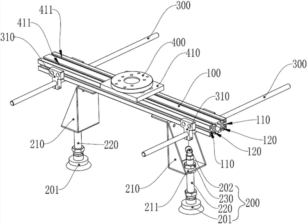
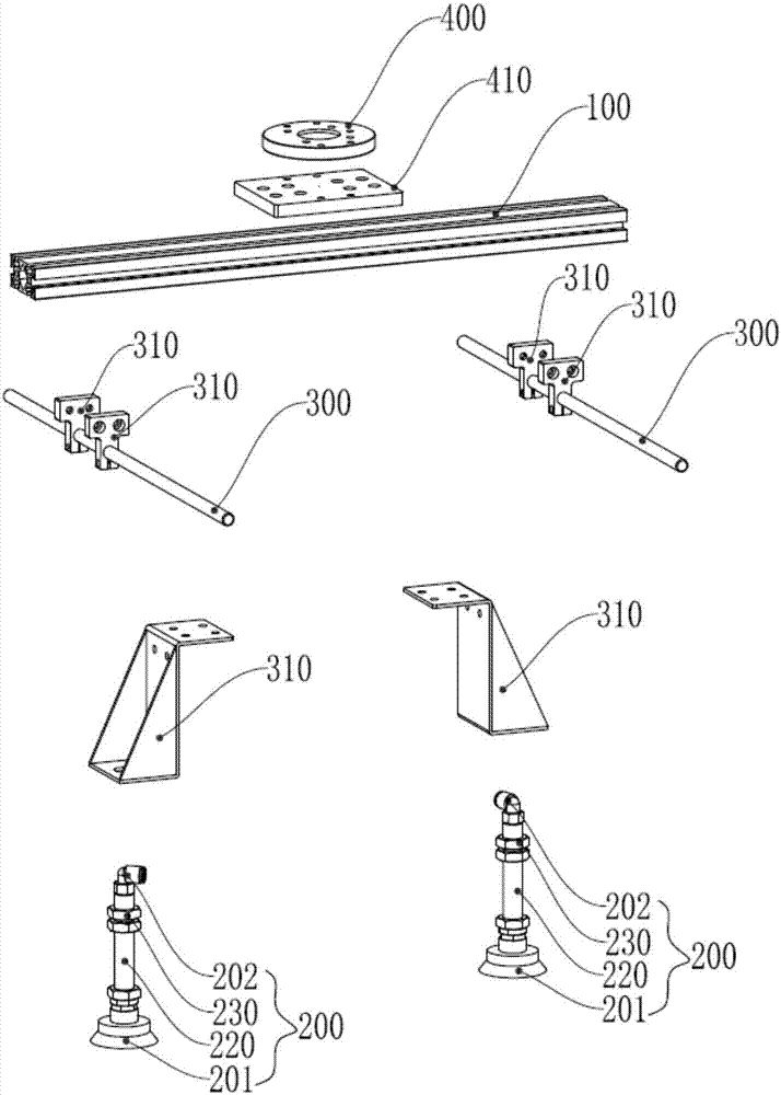
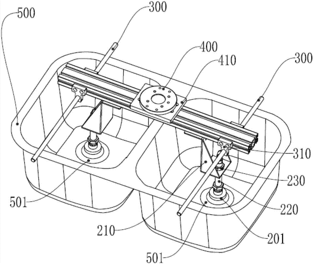
[0044] Such as Figure 1-3 As shown, a sink loading and unloading jig includes a main body beam 100, an adsorption device 200 and a balance correction rod 300; Some suction ends are located below the main body beam 100 and are set vertically downward to the main body beam 100; the balance correction rods 300 pass through both ends of the main body beam 100 vertically and horizontally respectively, and the balance correction rods 300 are arranged on Below the two ends of the main beam 100 and above the adsorption end of the adsorption device 200, so that the two ends of the balance correction rod 300 protrude from both sides of the adsorption device 200 respectively, when the When the adsorption end of the adsorption device 200 is adsorbed to the inner bottom surface of the water tank, the balance c...


PUM


Abstract

The invention relates to the field of machining, in particular to a water tank feeding and discharging clamp and a method for machining a water tank with the same. The water tank feeding and discharging clamp comprises a body cross beam, adsorption devices and balance correction rods. The adsorption devices are arranged at the two ends of the body cross beam correspondingly. Adsorption ends arranged at the lower ends of the adsorption devices are located below the body cross beam and are further vertically arranged downwards. The balance correction rods penetrate through the two ends of the body cross beam. When the adsorption ends of the adsorption devices are adsorbed onto the inner bottom face of the water tank, the balance correction rods can be tightly attached to the edges of the two sides of the upper end face of the water tank. The water tank feeding and discharging clamp is simple in structure, ingenious in design, easy and convenient to operate and meanwhile stable in clamping. By the adoption of the mode that feeding and discharging of the water tank is completed through the clamp, bumping and scratching caused in the feeding and discharging processes of the water tank can be avoided completely. Meanwhile, the clamping and adjusting frequency of a mechanical arm can be decreased, and the efficiency and precision in feeding and discharging of the water tank are greatly improved.

Description

technical field [0001] The invention relates to the field of mechanical processing, in particular to automatic grinding processing of water tanks. Background technique [0002] The sink is a very common washing basin in the kitchen and bathroom. It is generally made of metal or stone. The surface of the tank-shaped sink is very rough. It needs subsequent grinding and stamping to get the finished product on the market. [0003] When the water tank is being polished, it is necessary to load and lower the water tank to different grinding stations for many times. Some of the loading and unloading operations of the water tank in the production process in the prior art are completely by manual loading and unloading, and some are completed by the cooperation of manual and robotic hands. Manual loading and unloading is labor-intensive, prone to bumps, low production efficiency, and high defective rate; if the robot hand directly clamps the water tank for loading and unloading, the ...

Claims


Application Information

Patent Timeline
Patent Type & Authority Applications(China)
IPC IPC(8): B24B41/06B24B41/00B23P15/00
CPCB23P15/00B24B41/00B24B41/005B24B41/06
Inventor 吴学林罗智文周全霍锦添
Owner GUANGDONG LXD ROBOTICS CO LTD
Why Eureka
Try Eureka