
High-generating-efficiency sway bar for self-power-generation type new-energy automobile

A new energy vehicle, power generation efficiency technology, applied in the direction of generator/motor, piezoelectric effect/electrostrictive or magnetostrictive motor, electrical components, etc., can solve the problem of small moving range of conductors, low power generation efficiency and space constraints To achieve the effect of improving active adaptability, improving power generation efficiency, and adjusting speed block

Inactive Publication Date: 2017-11-21
XIHUA UNIV
View PDF1 Cites 0 Cited by
  • Summary
  • Abstract
  • Description
  • Claims
  • Application Information

AI Technical Summary

Problems solved by technology

[0003] In order to reduce the impact force when the wheel jumps vertically, it is generally desired to reduce the unsprung mass of the car as much as possible, but the torsion bar in the middle of the anti-roll bar is generally made of solid spring steel material, which is heavy and consumes a lot of materials. The bending moment transmitted by the connecting arm at the end is relatively large, so the connecting arm is generally made of cast iron or cast steel, and its cross-sectional size and weight are also relatively large. In order to reduce the unsprung mass, the weight of the anti-roll bar should be as small as possible
[0004] When the car is running normally, the amplitude of the vertical vibration of the wheel changes greatly. It is hoped that the torsional stiffness of the anti-roll bar will be low when the vertical amplitude of the wheel is small, so that the effect of the vertical spring and shock absorber can be fully exerted and the ride comfort can be improved. When the vertical amplitude of the wheel is large, it is desirable that the torsional stiffness of the anti-roll bar is high, which can improve the driving stability of the car, but the current anti-roll bar torsional stiffness is often a fixed value, which cannot take into account both situations at the same time. No. CN201511025991.X is an electronically controlled separated active anti-roll bar, including a left torsion bar, a right torsion bar, an active control module, a relative displacement sensor and a steering wheel angle sensor; wherein the active control module includes an ECU, a torque motor , left driving spur gear, right driving spur gear, left driving bevel gear, right driving bevel gear, left driven bevel gear, right driven bevel gear, left torsion bar gear, right torsion bar gear, planetary gear, left electromagnetic clutch, The planetary gear electromagnetic clutch and the right electromagnetic clutch can adjust the stiffness of the anti-roll bar through the active control module, but the structure of this patent is complex and there are many parts, which further increases the weight of the anti-roll bar, and the manufacturing and maintenance costs are high, making it difficult to large-scale promotion
[0005] And the power generation efficiency of the current vibration power generation device is also low, mainly because the principle of the current vibration power generation device is to generate current by cutting the magnetic induction line through the conductor, but limited by the space, the moving range of the conductor is generally small, so the power generation efficiency is very low

Method used


Image

  • High-generating-efficiency sway bar for self-power-generation type new-energy automobile
  • High-generating-efficiency sway bar for self-power-generation type new-energy automobile
  • High-generating-efficiency sway bar for self-power-generation type new-energy automobile

Examples


Embodiment Construction

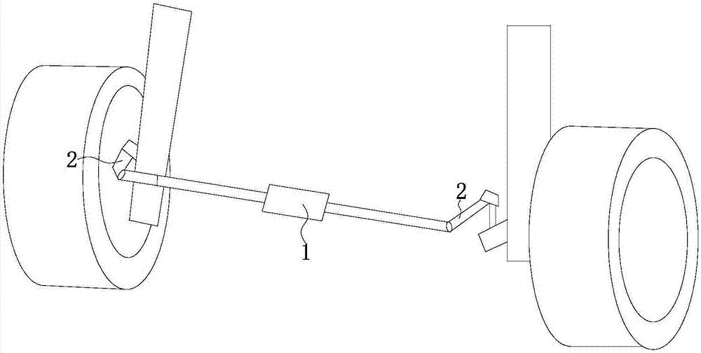
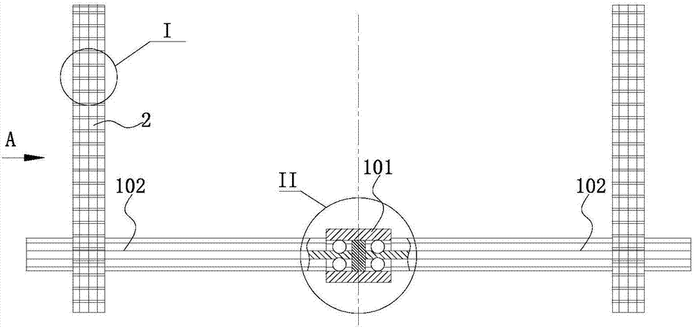
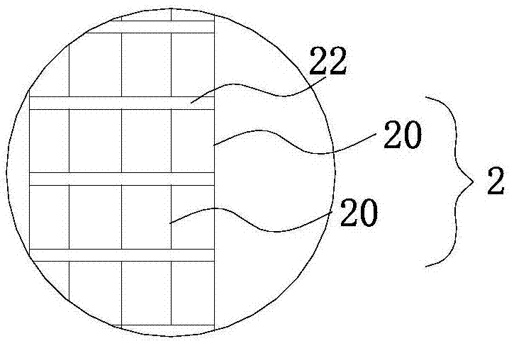
[0029] Such as Figure 1-Figure 10 The shown anti-roll bar for a self-generating new energy vehicle with high power generation efficiency includes a torsion bar 1 horizontally arranged below the vehicle frame along the transverse direction of the vehicle, and the torsion bar 1 includes a hollow central connecting cylinder 101;

[0030] The two ends of the central connecting cylinder 101 are respectively sleeved together with one end of a connecting torsion bar 102, and a force transmission block 103 is arranged between the two connecting torsion bars 102 in the central connecting cylinder 101, and the connecting torsion bar 102 can be moved along the The central connecting cylinder 101 slides in the axial direction and can rotate together with the central connecting cylinder 101. The two ends of the force transmission block 103 are respectively in contact with the ends of a connecting torsion bar 102; the connecting torsion bar 102 The other end passes through the side of one ...


PUM


Abstract

The invention specifically relates to an anti-roll bar for self-generating new energy vehicles with light weight, variable torsional rigidity and high power generation efficiency. The anti-roll bar includes a central connecting cylinder; the two ends of the central connecting cylinder are respectively sleeved together with one end of a connecting torsion bar, and the connecting torsion bar includes a central rod coaxially arranged with the central connecting cylinder, along the diameter of the central rod One or more rows of conductive rods are arranged in a circular array in the direction; the outer surface of the conductive rod passing through the connecting arm is also connected to one end of the arc-shaped torsion generating rod, and the described torsion generating rod includes two helical generating coils. DNA-style double helix structure formed by coiling; along the axial direction of the generating coil, multiple sets of generating units are arranged between two generating coils; the initial gap between the two permanent magnets in the generating unit can be set very small, when the gap changes When , the induced current generated is very large, which effectively improves the power generation efficiency.

Description

technical field [0001] The invention relates to the technical field of automobile suspension, in particular to an anti-roll bar for a self-generating new energy automobile with high power generation efficiency. Background technique [0002] The anti-roll bar is an important part of the independent suspension system of the automobile. It is generally installed on the front or rear axle of the automobile and connected to the left and right suspensions. Elastic torsion bar, the two ends of the torsion bar are connected with the suspension arm through the connecting arm, the torsion bar and the connecting arm form a U-shaped structure, when the body only moves vertically, the deformation of the suspension on both sides is the same, and the anti-roll bar does not work . When the body rolls, the suspension on both sides jumps inconsistently, the anti-roll bar twists, and the elastic force of the bar becomes the resistance to the continued roll of the body, playing the role of ant...

Claims


Application Information

Patent Timeline
IPC IPC(8): B60G21/055H02N2/18H02K35/04
CPCB60G21/055B60G21/0553H02K35/04H02N2/186
Inventor 陈子龙
Owner XIHUA UNIV
Learn More