Loader traction transmission system and transmission control method

A transmission system and traction force technology, applied in mechanical equipment, clutches, etc., can solve the problem of not being able to adjust the traction force transmission ratio, and achieve the effect of achieving uninterrupted power and increasing safety.

Inactive Publication Date: 2017-11-21
GUANGXI LIUGONG MASCH CO LTD
View PDF4 Cites 3 Cited by
  • Summary
  • Abstract
  • Description
  • Claims
  • Application Information

AI Technical Summary

Problems solved by technology

[0004] The technical problem to be solved by the present invention is to provide a loader traction transmission system and a transmission control method that can adjust the traction transmission ratio in view of the problem that the existing loader traction transmission system cannot adjust the traction transmission ratio

Method used


Image

  • Loader traction transmission system and transmission control method
  • Loader traction transmission system and transmission control method

Examples


Embodiment Construction

[0015] The specific implementation will be described below in conjunction with the accompanying drawings.

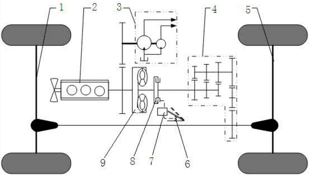
[0016] Such as figure 1 As shown, the traction force transmission system of the loader in the present embodiment includes an engine 2, a torque converter 9 driven by the engine 2, a gearbox 4, a front drive axle 1 connected to the gearbox 4 and a rear drive axle 5, including The brake system of the deceleration pedal 6, the clutch 8 and the clutch control device 7 for controlling the clutch, the input end of the clutch 8 is connected with the output end of the hydraulic torque converter 9, and the output end of the clutch 8 is connected with the input of the gearbox 4 end drive connection.

[0017] The clutch control device 7 includes a control valve connected to the oil circuit of the clutch oil cylinder, and the valve rod of the control valve is connected with the deceleration pedal.

[0018] In this embodiment, the clutch control device is a control valve controlled...


PUM


Abstract

The invention relates to the field of loader power transmission, aims to solve the problem that in a conventional loader traction transmission system, the traction transmission ratio cannot be regulated, and provides a loader traction transmission system which comprises an engine, a hydraulic torque converter, a gearbox, drive axles, a deceleration pedal, a clutch and a clutch control device, wherein the clutch is connected between the hydraulic torque converter and the gearbox; the deceleration pedal is connected with the clutch control device; when the deceleration pedal is within a front travel range, no brake action is taken by a brake system, and the engagement pressure of the clutch is controlled by the clutch control device according to the travel of the deceleration pedal; and when the deceleration pedal is within a rear travel range, the brake action is taken by the brake system according to the travel of the deceleration pedal. The loader traction transmission system provided by the invention has the advantages that the engagement pressure of the clutch is controlled through the front travel of the deceleration pedal, so that the trackslip of the clutch can be achieved, as well as the output rotational speed and the output torque can be changed and regulated; and when the deceleration is needed, the traction is regulated and reduced, so that the interruption in power transmission can be avoided and the safety of a complete loader can be improved.

Description

technical field [0001] The invention relates to a loader transmission, more specifically, to a loader traction force transmission system and a transmission control method. Background technique [0002] Loaders often carry out short-distance shoveling operations. It is often encountered that the loader has arrived at the truck, but the bucket of the loader has not been lifted. It is necessary to step on the brake and increase the accelerator of the engine at the same time. The kinetic energy of the whole machine is converted Heat energy is transferred to the bridge for braking energy. high temperature of the bridge. [0003] When the loader is working on the ramp while increasing the accelerator while walking and lifting, due to the high speed and stepping on the brake pedal, the driving power of the whole machine will be cut off immediately, and the whole machine will slide downhill. If the brake pedal does not stop If you step on the Panasonic and open it, the whole machi...

Claims


Application Information

Patent Timeline
Patent Type & Authority Applications(China)
IPC IPC(8): F16D48/02F16D48/06
CPCF16D48/02F16D48/066F16D2048/023F16D2500/10412F16D2500/31426F16D2500/50825F16D2500/70426
Inventor 王涛谭艳辉孙锋沈洪伟
Owner GUANGXI LIUGONG MASCH CO LTD
Why Eureka
Try Eureka