
Air-pipe-free fresh air system

A new air system, no air duct technology, applied in ventilation systems, heating and ventilation control systems, heating and ventilation safety systems, etc., can solve the problems of simple functions, difficult to meet the requirements of air dust removal and purification, and achieve reliable performance and structure Simple, fresh air effect

Pending Publication Date: 2017-11-21
重庆松池科技有限公司
View PDF11 Cites 0 Cited by
  • Summary
  • Abstract
  • Description
  • Claims
  • Application Information

AI Technical Summary

Problems solved by technology

However, this system has relatively high requirements on the air inlet and air supply port. The structure and function of the air supply port and air inlet in the prior art are simple, and it is difficult to meet the requirements of air dust removal and purification.

Method used


Image

  • Air-pipe-free fresh air system
  • Air-pipe-free fresh air system
  • Air-pipe-free fresh air system

Examples


Embodiment 1

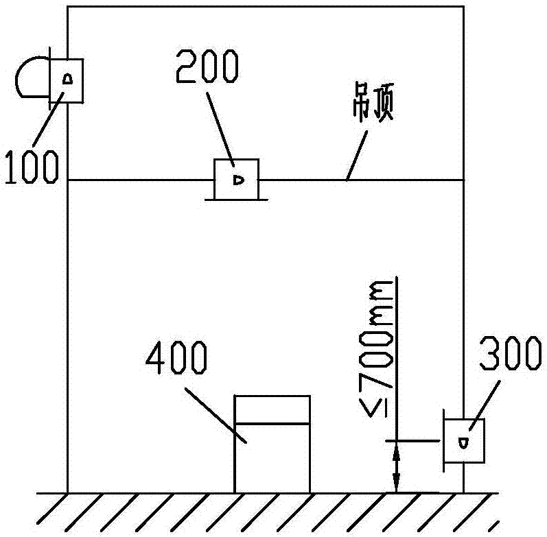
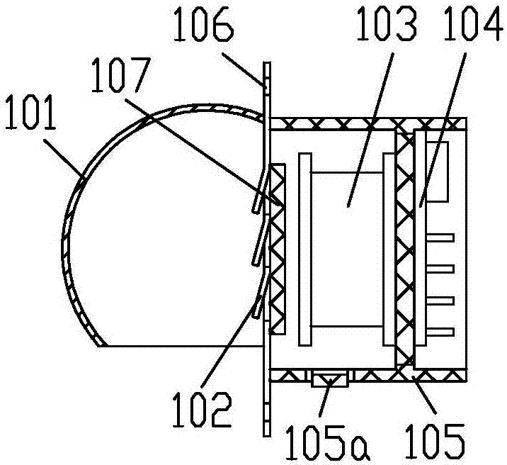
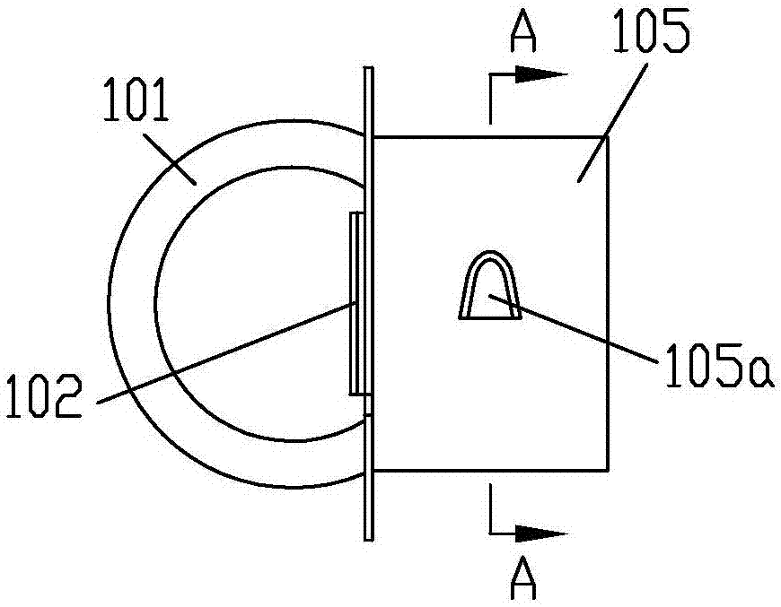
[0026] Example 1, see figure 1 , figure 2 , image 3 , Figure 4 , Figure 5 , Figure 6 , Figure 7 , a ductless fresh air system, comprising an air inlet 100 connected to a central controller, an air outlet 200, an exhaust outlet 300 and a negative ion air purifier 400, the air inlet 100 is arranged on the outer wall of the ceiling area of ​​the room, and the air outlet 200 is located on the suspended ceiling of the room, and the air outlet 300 is located on the outer wall below the suspended ceiling of the room, and its installation center is no more than 700mm from the ground of the room; The rain cap 101 is a spherical structure, and the air inlet on the rain cap 101 is downward and deviates from the center of the sphere; the mounting plate inlet section of the rain cap 101 is formed with a louver 102, and the louver 102 is integrally formed on the mounting plate by stamping; A protective net 107 is formed, and the protective net 107 is fixedly connected to the mou...

Embodiment 2

[0032] Example 2, see Figure 8 , the elastic claw 201a extends axially along the cylinder wall, and the free end of the elastic claw 201a faces the flange.

[0033] In this embodiment, the elastic claws 105 on the air inlet duct 105 can also be Figure 8 arranged with its free end facing the mounting plate.

[0034] The rest of the structure of this embodiment is the same as that of Embodiment 1, and will not be repeated here.


PUM


Abstract

The invention discloses an air-pipe-free fresh air system. The air-pipe-free fresh air system comprises an air inlet, an air supply opening and an air exhaust opening which are connected with a central control unit. The air inlet is formed in the position, in a room suspended ceiling area, of an outer wall, the air supply opening is formed in a suspended ceiling of a room, and the air exhaust opening is formed in the position, below the room suspended ceiling, of the outer wall. The air inlet is provided with a rainproof cap including a mounting disc. The rainproof cap is of a spherical structure, and the air inlet in the rainproof cap is downward and deviates from the sphere center. A louver is formed on the inlet section of the mounting disc of the rainproof cap, and a protection net is formed behind the louver. The air supply opening comprises an air supply air barrel with a flange. At least two elastic clamp jaws are arranged on the air supply air barrel, and the multiple elastic clamp jaws extend outwards from the barrel wall in the same axial direction or circumferential direction, and the multiple elastic clamp jaws and the barrel wall of the air supply air barrel form a whole. Containing space used when the elastic clamp jaws are pressed back is further arranged on the barrel wall of the air supply air barrel. The air-pipe-free fresh air system has the beneficial effects that the indoor air exchange effect is good, and indoor air freshness can be effectively kept for a long time; and the structure is simple, the performance is reliable, and air opening mounting and demounting are convenient.

Description

technical field [0001] The patent of the present invention relates to a fresh air system, especially a ductless fresh air system. Background technique [0002] The fresh air system is a system used to provide fresh air in a relatively closed indoor environment. It is mainly composed of an air inlet, an air supply outlet and an air outlet. It is located on the outer wall below the suspended ceiling of the room. This kind of fresh air system utilizes the ceiling space to form a fresh air inlet channel without the need to set up air ducts. It consumes less resources, requires less installation work, has low cost and low investment, and has broad application prospects. However, this system has relatively high requirements on the air inlet and the air supply port. The structure and function of the air supply port and the air inlet in the prior art are simple, and it is difficult to meet the requirements of air dust removal and purification. For this reason, improvements are req...

Claims


Application Information

Patent Timeline
Patent Type & Authority Applications(China)
IPC IPC(8): F24F7/007F24F3/16F24F11/02F24F13/00
CPCF24F7/007F24F13/00F24F8/108F24F8/10F24F8/30
Inventor 赵平
Owner 重庆松池科技有限公司
Learn More