
Multifunctional CT detection platform device

A detection platform and multi-functional technology, applied in the direction of measuring devices, instruments, scientific instruments, etc., can solve the problems of reduced production detection efficiency, poor detection effect, detection angle position limit, etc., to save equipment economic costs, improve production efficiency, The effect of widening the detection range

Pending Publication Date: 2017-11-21
DANDONG HUARI SCIENCE ELECTRIC CO LTD
View PDF0 Cites 2 Cited by
  • Summary
  • Abstract
  • Description
  • Claims
  • Application Information

AI Technical Summary

Problems solved by technology

[0002] At present, the current CT detection platform in the field of X-ray CT mainly uses the C-arm bracket to carry the X-ray machine and the receiver, and performs transillumination scanning up and down, or uses the multi-axis frame vehicle-mounted X-ray machine and the receiver to adjust the detection distance up and down. The detection workpiece is placed on a multi-axis platform and the scanning detection of the workpiece is completed by moving back and forth, up and down and platform rotation. Due to structural limitations, this detection platform cannot scan and detect long plates and long pipes, nor can it be scanned by a single device. The workpieces of various specifications are inspected, and the inspection variety is single, and due to the relatively simple structure, the detection angle position is limited, and the detection effect is poor. If you want to complete the scanning inspection of different workpieces, you need to purchase professional inspection equipment separately, which will greatly increase the cost. And greatly reduce the production detection efficiency

Method used


Image

  • Multifunctional CT detection platform device
  • Multifunctional CT detection platform device
  • Multifunctional CT detection platform device

Examples


Embodiment Construction

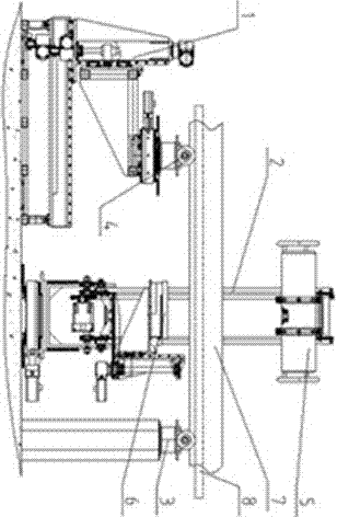
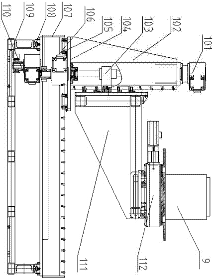
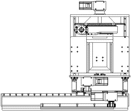
[0014] Such as Figure 1-Figure 7A multifunctional CT detection platform device is shown, and the multifunctional CT detection platform device includes: a small workpiece turntable 1, a ring-shaped host detection platform 2, a fixed conveying roller 3, and a small conveying roller 4; the small workpiece turntable 1 is installed and fixed on On the leftmost horizontal ground, the ring main engine detection platform 2 is fixed on the middle ground, the fixed conveying roller 3 is fixed on the ground on the right side of the axis position, the small conveying roller 4 is fixed on the turntable on the small workpiece turntable 1, and the three groups of components are on the Symmetrically distributed on the same axis, adjust the height of the turntable on the small workpiece turntable 1 so that the small conveying roller 4 and the fixed conveying roller 3 are at the same height; the small workpiece turntable 1 includes: lifting reducer motor 101, stand 102, lifting screw Guide rai...


PUM


Abstract

The invention discloses a multifunctional CT detection platform device. The multifunctional CT detection platform device comprises a small workpiece turnplate, an annular host detection platform, a fixed conveying roll and a small conveying roll. Transverse and longitudinal movement of the small workpiece turnplate is adjusted, the lifting height of a motor turnplate is adjusted, a workpiece is placed, the height of a receiver holder in the annular host detection platform is adjusted in a driving manner to achieve an optimum detection distance, an annular gear rail is driven to rotate by controlling an annular driving gear motor in the annular host detection platform so as to drive a ray machine and a receiver which are mounted on the annular gear rail to rotate, and the ray machine and the receiver start working synchronously to complete an X-ray CT scanning detection process of the workpiece. The multifunctional CT detection platform device can detect various small workpieces, long plates and pipe workpieces, so that the detection range is widened; the multifunctional CT detection platform device not only improves the detection effect, but also greatly reduces the economic cost of equipment while the production efficiency is greatly improved; the multifunctional CT detection platform device is suitable for wide popularization.

Description

technical field [0001] The invention relates to an X-ray detection device, in particular to a multifunctional CT detection platform device. Background technique [0002] At present, the current CT detection platform in the field of X-ray CT mainly uses the C-arm bracket to carry the X-ray machine and the receiver, and performs transillumination scanning up and down, or uses the multi-axis frame vehicle-mounted X-ray machine and the receiver to adjust the detection distance up and down. The detection workpiece is placed on a multi-axis platform and the scanning detection of the workpiece is completed by moving back and forth, up and down and platform rotation. Due to structural limitations, this detection platform cannot scan and detect long plates and long pipes, nor can it be scanned by a single device. The workpieces of various specifications are inspected, and the inspection variety is single, and due to the relatively simple structure, the detection angle position is lim...

Claims


Application Information

Patent Timeline
Patent Type & Authority Applications(China)
IPC IPC(8): G01N23/04
CPCG01N23/046
Inventor 孙毅尚宝刚刘元元孙煕辰隋莹莹
Owner DANDONG HUARI SCIENCE ELECTRIC CO LTD
Learn More