
Multi-line rotary scanning detection method

A technology of rotating scanning and detection method, applied in the field of optical ranging, can solve the problems of reducing efficiency, chromaticity and brightness interference, glare, etc., achieving the effect of simple structure design and avoiding interference

Pending Publication Date: 2017-11-21
BENEWAKE BEIJING TECH CO LTD
View PDF8 Cites 27 Cited by
  • Summary
  • Abstract
  • Description
  • Claims
  • Application Information

AI Technical Summary

Problems solved by technology

The above-mentioned multi-line laser radar system in the prior art is composed of 64 individual ranging systems (laser light sources / detector pairs), and the individual laser light sources / detectors need to be set at fixed angles, which is complicated to manufacture
However, when multiple lasers are used as the detection light source, it is preferable during the detection process (see page 6 of the above-mentioned prior art specification) to emit only a few lasers or only one laser at a time. Luminance interference, or dazzle when a laser beam encounters a returning laser beam, and firing only a few lasers at a time reduces detection efficiency at the same angle
In addition, the 64 laser diodes only perform distance detection on 64 angles in the same vertical direction, and cannot expand in the horizontal direction at the same angle where the lidar is located.

Method used


Image

  • Multi-line rotary scanning detection method
  • Multi-line rotary scanning detection method
  • Multi-line rotary scanning detection method

Examples


Embodiment Construction

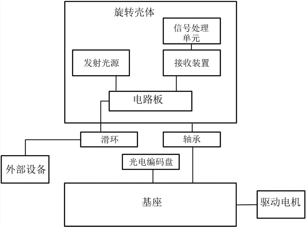
[0026] The present application relates to a multi-line rotary scanning detection method, which realizes multi-line scanning within a range of 360 degrees and obtains distance information of three-dimensional point clouds. as attached Figure 1-2 As shown, the multi-line rotary scanning detection device includes:

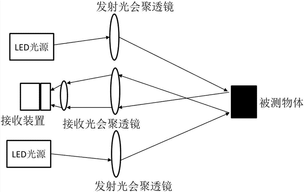
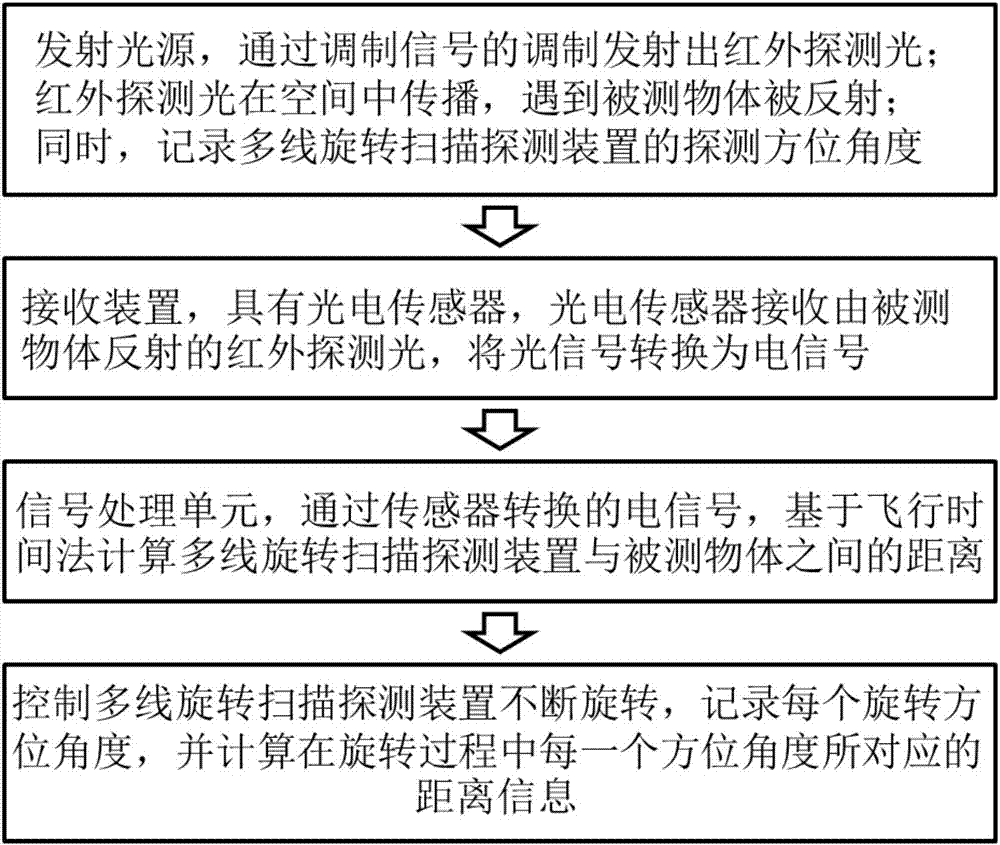
[0027] The emitting light source is fixed inside the rotating housing and emits infrared detection light through the modulation of the modulation signal. The infrared detection light propagates in space and is reflected when it encounters the measured object;

[0028] The receiving device is fixed inside the rotating housing and has a photoelectric sensor, which receives the infrared detection light reflected by the measured object and converts the optical signal into an electrical signal;

[0029] The signal processing unit is electrically connected with the photoelectric sensor, and calculates the distance between the multi-line rotary scanning detection device an...


PUM

PropertyMeasurementUnit
Divergence angleaaaaaaaaaa

Abstract

The invention relates to a multi-line rotary scanning detection method which is used for measuring the distance between a multi-line rotary scanning detection device and a detected object. The multi-line rotary scanning detection method comprises the steps that an emitting light source emits infrared detection light, and the detection azimuth of the multi-line rotary scanning detection device is recorded; a photoelectric sensor receives the infrared detection light reflected by the detected object; a signal processing unit calculates the distance between the multi-line rotary scanning detection device and the detected object based on a time of flight method; and the detection device continuously rotates and records azimuth and distance information. According to the invention, an LED is adopted to act as the light source to emit a light beam with a small divergence angle, thereby avoiding mutual interference caused by using multiple laser light sources in the prior art. The sensor adopts an array sensor, thereby performing scanning on multiple positions in the horizontal and vertical directions, and acquiring multi-line scanning three-dimensional point cloud distance data in the 360-degree field of view. The emitting light source and the receiving device are simple in structural design in the operating process.

Description

technical field [0001] The present application relates to the field of optical ranging, in particular, to a multi-line rotary scanning detection device and method. Background technique [0002] The optical scanning ranging device is a device that uses collimated beams to perform non-contact scanning ranging through triangulation, Time of Flight (TOF for short) and other methods. At present, a common time-of-flight optical scanning ranging device includes: a light emitting module, an optical lens, a chip for receiving and processing signals, a motor, a bearing and a conductive slip ring. The light emitting module emits a single light beam, the optical lens is located on the optical path of the light emitting module, the collimated light beam is emitted to the surface of the object to be measured, and the light beam is reflected to the receiving chip after encountering obstacles, and the receiving chip transmits it to the receiving side through measurement. The distance betwe...

Claims


Application Information

Patent Timeline
IPC IPC(8): G01S17/36G01S7/481G01S7/491
CPCG01S7/4817G01S7/4911G01S7/4913G01S17/36
Inventor 郑凯王瑞李远
Owner BENEWAKE BEIJING TECH CO LTD
Features
  • Generate Ideas
  • Intellectual Property
  • Life Sciences
  • Materials
  • Tech Scout
  • Unparalleled Data Quality
  • Higher Quality Content
  • 60% Fewer Hallucinations
Learn More