Motor stator, three-phase permanent magnet motor, and compressor

A motor stator, permanent magnet motor technology, applied in the field of compressors

Pending Publication Date: 2017-11-21
GUANGDONG MEIZHI COMPRESSOR
View PDF0 Cites 0 Cited by
  • Summary
  • Abstract
  • Description
  • Claims
  • Application Information

AI Technical Summary

Problems solved by technology

[0005] The main purpose of the present invention is to provide a motor stator, a three-phase permanent magnet motor and a compressor, aiming to solve the technical problem of how to control the back EMF coefficient

Method used


Image

  • Motor stator, three-phase permanent magnet motor, and compressor
  • Motor stator, three-phase permanent magnet motor, and compressor
  • Motor stator, three-phase permanent magnet motor, and compressor

Examples


Embodiment Construction

[0033] The following will clearly and completely describe the technical solutions in the embodiments of the present invention with reference to the accompanying drawings in the embodiments of the present invention. Obviously, the described embodiments are only part of the embodiments of the present invention, not all of them. Based on the embodiments of the present invention, all other embodiments obtained by persons of ordinary skill in the art without making creative efforts belong to the protection scope of the present invention.

[0034] It should be noted that all directional indications (such as up, down, left, right, front, back...) in the embodiments of the present invention are only used to explain the relationship between the components in a certain posture (as shown in the accompanying drawings). Relative positional relationship, movement conditions, etc., if the specific posture changes, the directional indication will also change accordingly.

[0035] In addition,...


PUM


Abstract

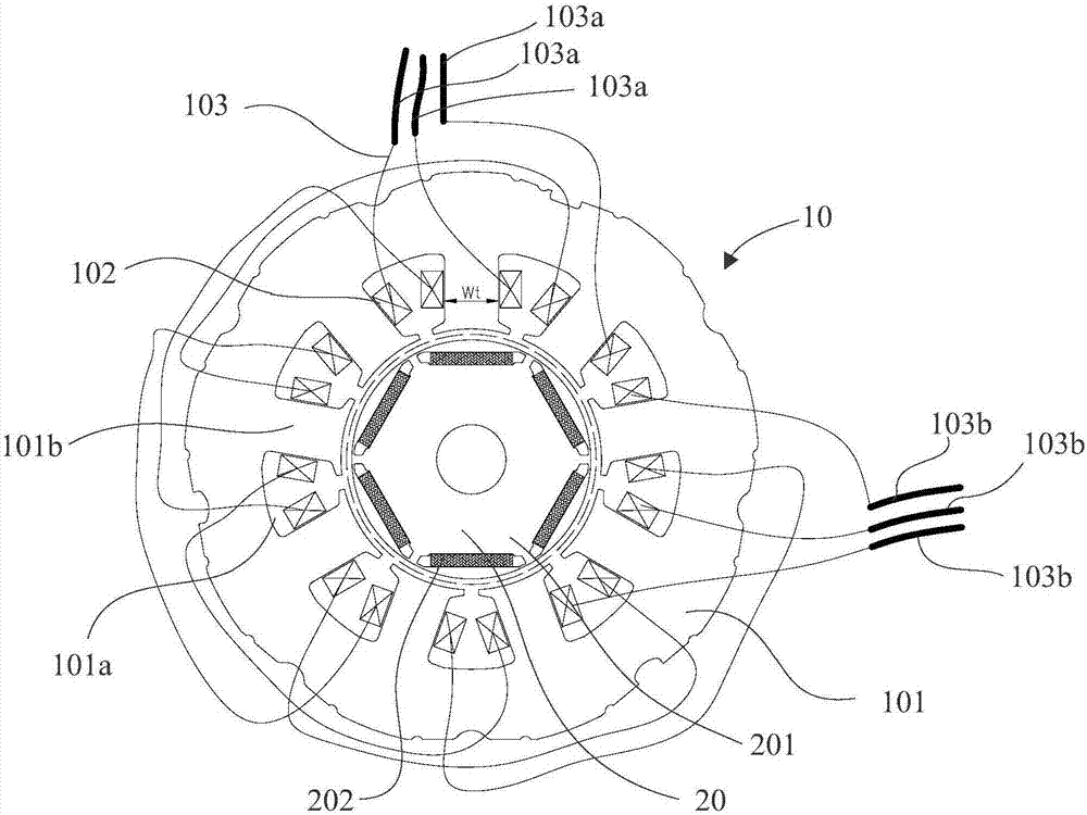
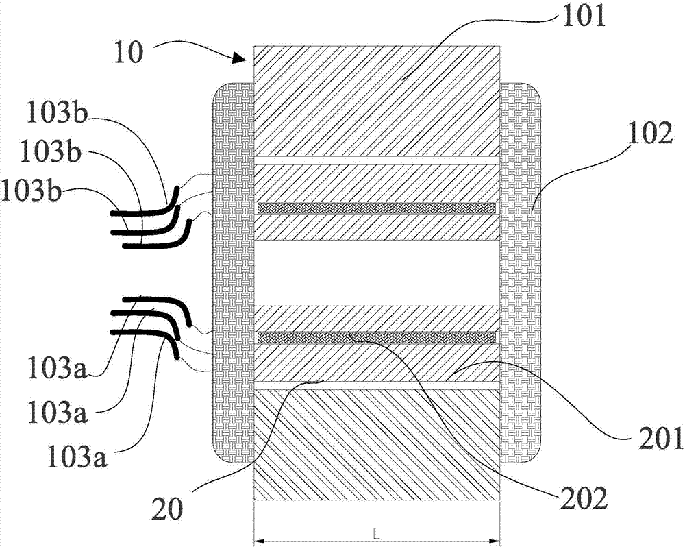
The invention discloses a motor stator, a three-phase permanent magnet motor, and a compressor. The number n of parallel-connected branches of each phase of a stator winding is determined according to a parameter [psi], wherein [psi]=Bt x Wt x Z x L x N x k. When the [psi] is relatively high, phase magnetic chain can be reduced through setting a value of n, to make the phase magnetic chain in a certain range, so that a back electromotive force coefficient is also controlled in a certain range, and a permanent magnet motor has high back electromotive force under slow-speed of revolution and has low back electromotive force under high-speed of revolution. The motor is ensured to have excellent performance under slow-speed of revolution and high-speed of revolution.

Description

technical field [0001] The invention relates to the technical field of compressors, in particular to a motor stator, a three-phase permanent magnet motor and a compressor. Background technique [0002] The permanent magnet motor for the compressor is driven and controlled by a frequency converter. The higher the back EMF coefficient of the permanent magnet motor, the lower the operating current before entering the field weakening control, which is beneficial to reduce the loss of the inverter; while the bus voltage output by the inverter has a limit value, the back EMF coefficient of the permanent magnet motor is higher At this time, it is easy to enter the field weakening area, the operating current increases, the loss increases, and it cannot even operate reliably at high speeds. [0003] Therefore, permanent magnet motors with high back EMF coefficient at low speed and low back EMF at high speed have always been the focus of research in the industry. [0004] The above ...

Claims


Application Information

Patent Timeline
IPC IPC(8): H02K1/14H02K3/28H02K3/04F04C23/02
CPCH02K1/14H02K3/04H02K3/28F04C23/02H02K2213/03
Inventor 乔正忠徐飞邱小华宋万杰
Owner GUANGDONG MEIZHI COMPRESSOR
Why Eureka
Try Eureka