Supercharge Your Innovation With Domain-Expert AI Agents!

A microwave frequency conversion circuit and frequency converter

A microwave frequency conversion and circuit technology, which is applied to electrical components, multi-frequency modulation and conversion, diversity/multi-antenna systems, etc. Power consumption, the effect of increasing the service life

Active Publication Date: 2020-02-21
CCT SPACE INFO IND & TECH LTD
View PDF5 Cites 0 Cited by
  • Summary
  • Abstract
  • Description
  • Claims
  • Application Information

AI Technical Summary

Problems solved by technology

[0003] The embodiment of the present invention provides a microwave frequency conversion circuit and a frequency converter, aiming to solve the problem that the existing technology cannot effectively reduce the power loss generated by the components during operation, resulting in an increase in the power of the product during use. Consumption, and reduce the life of the components of the product in the long-term use process

Method used


Image

  • A microwave frequency conversion circuit and frequency converter
  • A microwave frequency conversion circuit and frequency converter
  • A microwave frequency conversion circuit and frequency converter

Examples


Embodiment 1

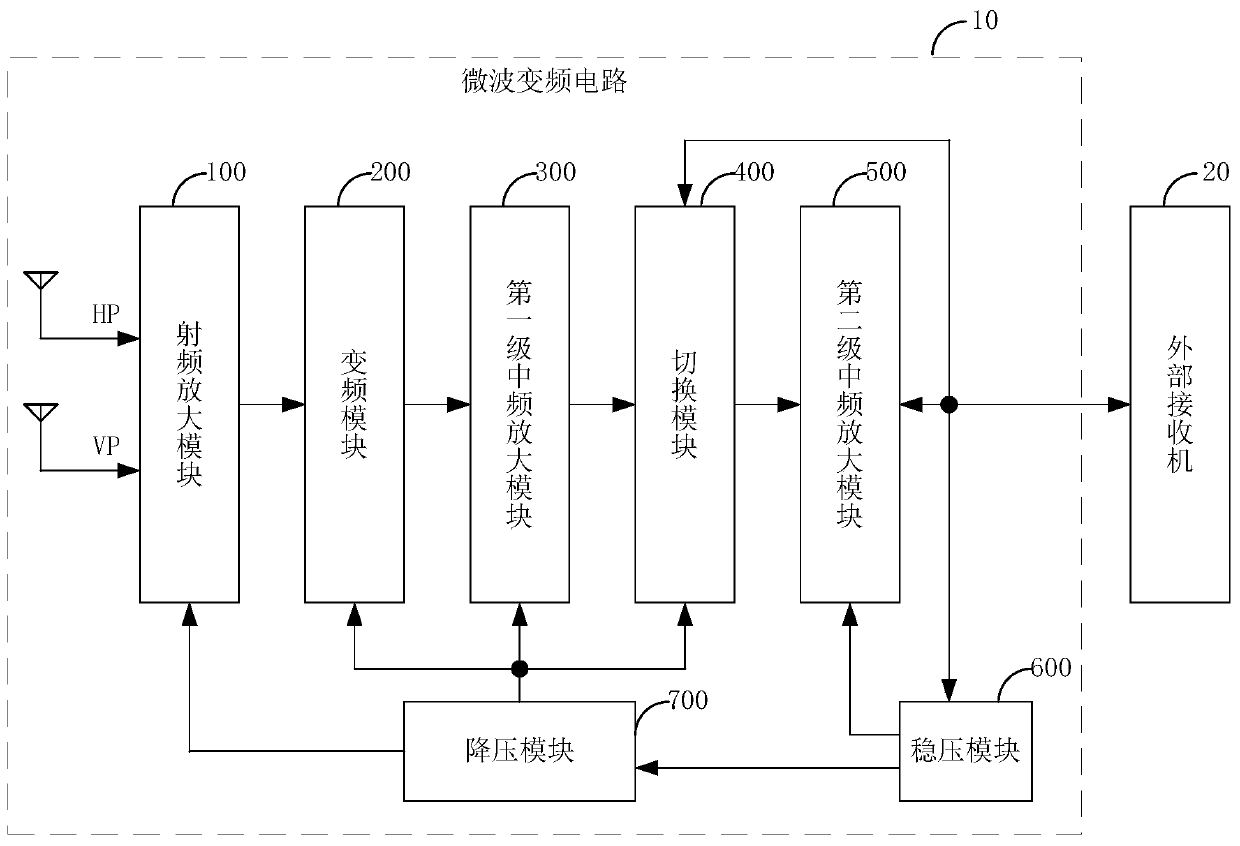
[0030] figure 1 The structure of a microwave frequency conversion circuit 10 provided by an embodiment of the present invention is shown. For the convenience of description, only the parts related to the embodiment of the present invention are shown, and the details are as follows:

[0031] Such as figure 1 As shown, a microwave frequency conversion circuit 10 provided by the embodiment of the present invention includes a radio frequency amplification module 100, a frequency conversion module 200, a first-stage intermediate frequency amplification module 300, a switching module 400, a second-stage intermediate frequency amplification module 500, and a voltage stabilization module 600 and step-down module 700.

[0032] The radio frequency amplification module 100, the frequency conversion module 200, the first stage intermediate frequency amplification module 300, the switching module 400 and the second stage intermediate frequency amplification module 500 are sequentially con...

Embodiment 2

[0037] This embodiment is a further refinement of the structure of the microwave frequency conversion circuit 10 provided in the first embodiment.

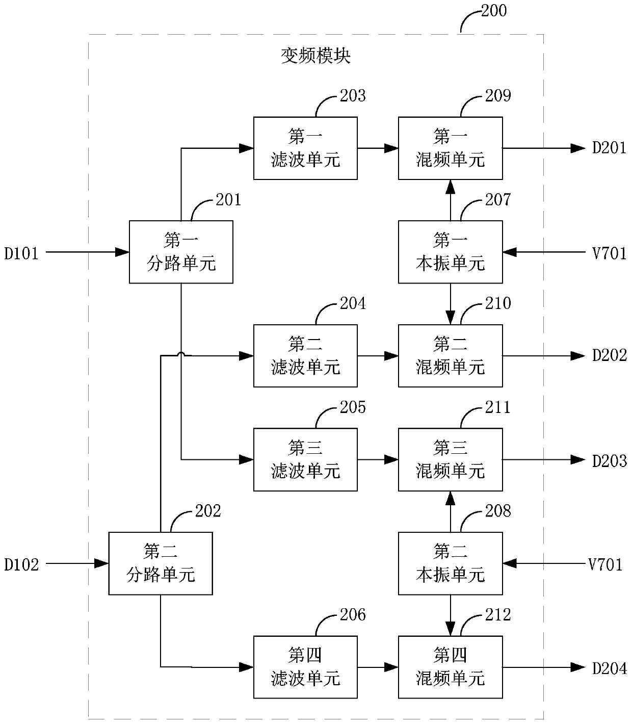
[0038] Such as figure 2 As shown, in one embodiment, figure 1 The radio frequency amplifying module 100 includes a first radio frequency amplifying unit 110 and a second radio frequency amplifying unit 120 .

[0039] The input terminal of the first radio frequency amplifying unit 110 is connected to the horizontal polarization signal HP, the output terminal D101 of the first radio frequency amplifying unit 110 is connected with the first input terminal D101 of the frequency conversion module 200, and a plurality of power supply terminals of the first radio frequency amplifying unit 110 (V702-V707) are respectively connected to multiple output terminals (V702-V707) of the step-down module 700 in one-to-one correspondence, and the first radio frequency amplifying unit 110 amplifies the horizontally polarized signal HP according to...

Embodiment 3

[0068] This embodiment is a further refinement of the structure of the microwave frequency conversion circuit 10 provided in the second embodiment.

[0069] Such as Figure 9 shown, provides figure 2 The circuit structure of an embodiment of the radio frequency amplification module 100 in FIG.

[0070] The first radio frequency amplifying unit 110 includes a first amplifying tube Q1, a second amplifying tube Q2, a third amplifying tube Q3, a capacitor C1, a capacitor C2, a capacitor C3, a capacitor C4, a capacitor C5, a capacitor C6, a capacitor C7, a capacitor C8, a capacitor C9, capacitor C10, capacitor C11, capacitor C12, resistor R1, resistor R2, resistor R3, resistor R4, resistor R5 and resistor R6.

[0071] The control end of the first amplifying tube Q1 is connected with the first end of the resistor R1 to form the input end of the first radio frequency amplifying unit 110, and the second end of the resistor R1 is connected with the first end of the capacitor C7 to f...


PUM


Abstract

The invention relates to the technical field of microwave electronics, and discloses a microwave frequency conversion circuit and a frequency converter. The invention includes a radio frequency amplifier module, a frequency conversion module, a first-stage intermediate frequency amplifier module, a switching module, a second-stage intermediate frequency amplifier module, a voltage regulator module and a step-down module. Powering the RF amplifier module, frequency conversion module, first-stage intermediate frequency amplifier module and switching module can effectively reduce the current and voltage required by the product's own components according to their specifications, which not only reduces power consumption, but also increases the components in the product. service life.

Description

technical field [0001] The invention relates to the technical field of microwave electronics, in particular to a microwave frequency conversion circuit and a frequency converter. Background technique [0002] With the rapid development of microwave electronic technology, microwave frequency converters are widely used in this industry. However, the existing frequency converter cannot effectively reduce the power loss generated by the components during operation, which not only increases the power consumption of the product during use, but also reduces the power consumption of the product components during long-term use. life. Contents of the invention [0003] The embodiment of the present invention provides a microwave frequency conversion circuit and a frequency converter, aiming to solve the problem that the existing technology cannot effectively reduce the power loss generated by the components during operation, resulting in an increase in the power of the product duri...

Claims


Application Information

Patent Timeline
Patent Type & Authority Patents(China)
IPC IPC(8): H04B1/26H04B7/10H03D7/16H04B7/08
CPCH03D7/16H04B1/26H04B7/08H04B7/10Y02D30/70
Inventor 陈进刘俊杰潘雄广
Owner CCT SPACE INFO IND & TECH LTD
Features
  • R&D
  • Intellectual Property
  • Life Sciences
  • Materials
  • Tech Scout
  • Unparalleled Data Quality
  • Higher Quality Content
  • 60% Fewer Hallucinations
Learn More