Supercharge Your Innovation With Domain-Expert AI Agents!

Network TCP flow control method

A flow control and network technology, which is applied in the direction of data exchange network, digital transmission system, electrical components, etc., can solve the problems of transmission rate drop, data packet retransmission, waste of network bandwidth, etc., to improve control granularity, overcome retransmission, The effect of improving the utilization rate

Inactive Publication Date: 2017-11-21
杨怀艳
View PDF0 Cites 2 Cited by
  • Summary
  • Abstract
  • Description
  • Claims
  • Application Information

AI Technical Summary

Problems solved by technology

The traditional method has the following shortcomings: 1. The queuing delay and scheduling delay of the queue increase the round-trip delay of the data packet
Especially when the scale of the queue is large, the delay will increase, which may affect the business flow with high real-time requirements; 2. Packet loss will cause the retransmission of the data packet of the TCP flow, wasting network bandwidth and reducing network bandwidth Utilization of
At the same time, because the congestion control mechanism of the TCP protocol will take measures to suppress the sending rate of packet loss, the sending rate of TCP will decrease automatically, resulting in excessive bandwidth occupation of UDP flow, resulting in the unfairness of TCP flow and UDP flow; 3. Traffic The setting of the control strategy is not flexible enough, and the strategy indicators relied on are not comprehensive enough
Most flow control systems cannot distinguish protocols at different levels, especially the business types of the application layer; 4. It is difficult to ensure that the flow control between business flows is independent of each other, and it is impossible to adopt an independent flow control structure for a single business flow

Method used


Image

  • Network TCP flow control method

Examples


Embodiment Construction

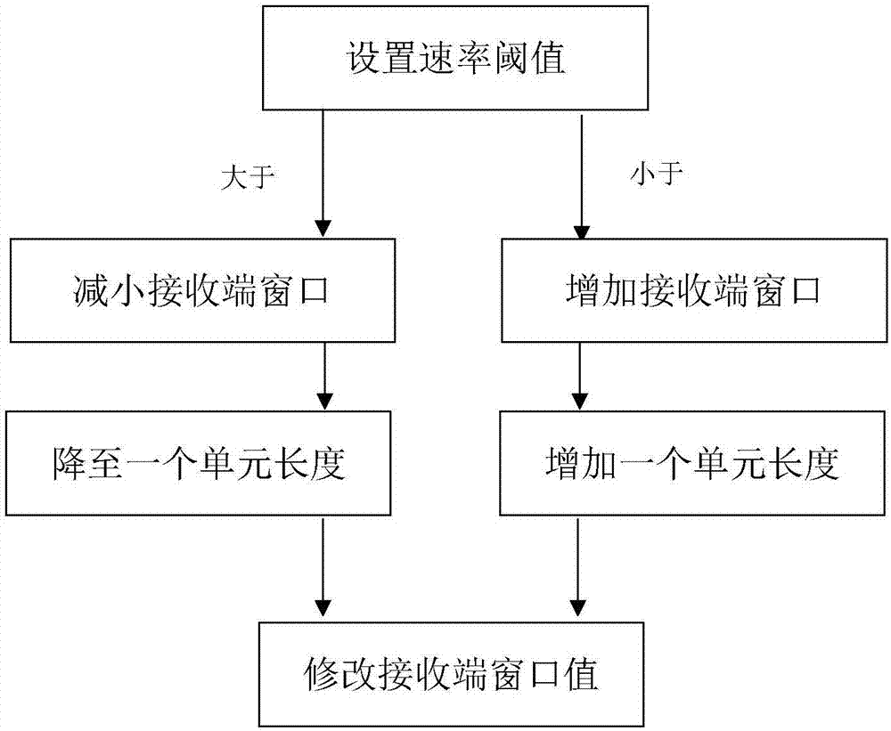
[0027] An embodiment of the present invention will be described below in conjunction with the accompanying drawings.

[0028] Such as figure 1 As shown, the present invention: when the actual rate is greater than the reserved rate threshold, reduce the receiving end window; when the actual rate is less than the reserved rate threshold, gradually increase the receiving end window. At the same time, different levels of control are adopted for the two cases of exceeding the low rate threshold and exceeding the high rate threshold. When the actual rate exceeds the high rate threshold, the window at the receiving end is immediately reduced to a unit length. The purpose is to ensure that the actual rate cannot be exceeded. If the reserved rate threshold is exceeded, when the actual rate is lower than the low rate threshold, the window at the receiving end is increased by one unit length, and the transmission rate is gradually restored. Under the action of this control mechanism, th...


PUM


Abstract

The invention relates to a network TCP flow control method which comprises the steps of setting a speed threshold for a speed pipe; when the actual speed is higher than a preset speed threshold, reducing a receiving end window; when the actual speed is lower than the preset speed threshold, gradually increasing the receiving end window; performing different controlling measures with different degrees on two limit exceeding conditions of exceeding a low speed threshold and exceeding a high speed threshold; and modifying the value of the receiving end window. The network TCP flow control method is advantageous in that in a flow control process, through modifying the value of the receiving end window in an ACK acknowledging package, a purpose of adjusting transmitting rate by the transmitting end is realized, thereby realizing flow controlling to the TCP flow. Furthermore in a dynamic receiving end window modifying process, real-time sampling is performed on the length of the transmitting end TCP message for estimating the length of the current TCP message segment, and the length of the current TCP message segment is used as a least unit for modifying the value of the receiving end window, thereby improving control granularity. Because no data packet loss occurs in a flow control process, a data packet retransmission problem is overcome in a relatively good manner, and network bandwidth utilization rate is improved.

Description

technical field [0001] The invention belongs to the field of network control, in particular to a network TCP flow control method. Background technique [0002] Most of the traditional flow control methods are flow control algorithms based on the queue model, such as RED and WFQ, which adjust the service flow rate by caching or discarding data packets, and complete the bandwidth allocation of different types of service flows through queue priority scheduling. The flow provides different services and realizes service quality assurance for mission-critical services. The traditional method has the following disadvantages: 1. The queuing delay and scheduling delay of the queue increase the round-trip delay of the data packet. Especially when the scale of the queue is large, the delay will increase, which may affect the business flow with high real-time requirements; 2. Packet loss will cause the retransmission of the data packet of the TCP flow, wasting network bandwidth and red...

Claims


Application Information

Patent Timeline
IPC IPC(8): H04L12/801H04L12/815H04L47/22
CPCH04L47/193H04L47/225
Inventor 杨怀艳
Owner 杨怀艳
Features
  • R&D
  • Intellectual Property
  • Life Sciences
  • Materials
  • Tech Scout
  • Unparalleled Data Quality
  • Higher Quality Content
  • 60% Fewer Hallucinations
Learn More