Special vertical crushing device

A crushing device, vertical technology, applied in the field of special vertical crushing device, can solve the problems of easy blockage in the inner and upper part of the dryer, affecting normal production, high viscosity, etc., to achieve convenient installation and disassembly, long service life, and effective Good results

Inactive Publication Date: 2017-11-24
丛晓庆
View PDF0 Cites 7 Cited by
  • Summary
  • Abstract
  • Description
  • Claims
  • Application Information

AI Technical Summary

Problems solved by technology

Both the feed pipe and the exhaust pipe are located on the top of the shell, and the inside of the shell is equipped with multi-component materials and sliding material basins from top to bottom. During operation, high-temperature hot air enters the lower part of the shell through the air inlet, and passes through , and finally discharged through the discharge pipe. Since the material falling from the feed pipe into the upper part of the material cone in the shell is the wettest, the high-temperature hot air dries the material from the bottom to the top of the shell, so that the upper part of the shell The temperature is low, so when drying materials with high viscosity and large particles, the materials are easy to block the inner and upper parts of the dryer, affecting normal production

Method used


Image

  • Special vertical crushing device

Examples


Embodiment 1

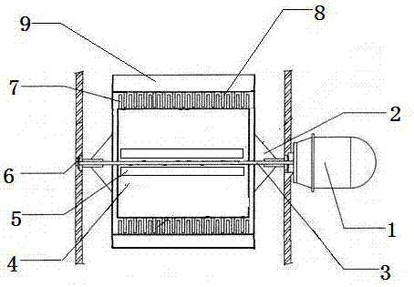
[0013] This embodiment provides a dedicated vertical crushing device, which is characterized in that: the special vertical crushing device includes a driving machine (1), a connecting fixed plate (2), a rotating shaft (3), an inner rotating crushing and drying cylinder (4), discharge port (5), shaft seat (6), inner cylinder crushing teeth (7), outer rotating crushing and drying cylinder (8), outer cylinder crushing teeth (9);

[0014] Among them: the device is composed of a driving machine (1) and a drying and crushing system. The power output end of the driving machine (1) is fixedly connected to the rotating shaft (3), and the other end of the rotating shaft (3) is rotatably connected to the shaft seat (6), and the rotating shaft (3) ) by connecting the fixed plate (2) to fixedly install the inner rotating crushing and drying cylinder (4), and the outer edge of the inner rotating crushing and drying cylinder (4) is evenly equipped with inner cylinder crushing teeth (7).

[0...

Embodiment 2

[0018] A special vertical crushing device, characterized in that the special vertical crushing device includes a driving machine (1), a connecting fixed plate (2), a rotating shaft (3), an inner rotating crushing and drying cylinder (4), an outlet Material opening (5), shaft seat (6), inner cylinder crushing teeth (7), outer rotating crushing and drying cylinder (8), outer cylinder crushing teeth (9);

[0019] Among them: the device is composed of a driving machine (1) and a drying and crushing system. The power output end of the driving machine (1) is fixedly connected to the rotating shaft (3), and the other end of the rotating shaft (3) is rotatably connected to the shaft seat (6), and the rotating shaft (3) ) by connecting the fixed plate (2) to fixedly install the inner rotating crushing and drying cylinder (4), and the outer edge of the inner rotating crushing and drying cylinder (4) is evenly equipped with inner cylinder crushing teeth (7).

[0020] The driving machine ...


PUM


Abstract

A special vertical crushing device, characterized in that: the special vertical crushing device includes a driving machine, a connecting fixed plate, a rotating shaft, an inner rotating crushing and drying cylinder, a discharge port, a shaft seat, an inner cylinder crushing tooth, an outer Rotary crushing and drying cylinder, outer cylinder crushing teeth; wherein: the device is composed of a driving machine and a drying and crushing system, the driving machine is a hydraulic driving machine or a motor, the power output end of the driving machine is fixedly connected to the rotating shaft, and the other end of the rotating shaft is connected The shaft seat and the rotating shaft are fixedly installed with the inner rotary crushing and drying cylinder by connecting the fixed plate. The inner cylinder crushing teeth are uniformly arranged on the outer edge of the inner rotary crushing and drying cylinder, and the inner cylinder crushing teeth are evenly arranged on the inner side of the outer rotary crushing and drying cylinder. The outer cylinder crushing teeth on the top, and the outer rotary crushing and drying cylinder are fixedly set on the inner rotating crushing and drying cylinder. The advantages of the present invention: the special vertical crushing device described in the present invention has reasonable and simple structural design, convenient installation and disassembly, convenient maintenance, time-saving and labor-saving, high transmission efficiency, no energy loss caused by friction, and no friction between parts. Hard impact, long service life of parts, good crushing and drying effect.

Description

technical field [0001] The invention relates to a device for drying materials at high temperature, and in particular provides a special vertical crushing device. Background technique [0002] Now, the vertical dryer is one of the commonly used equipment for drying materials in cement production enterprises. . Both the feed pipe and the exhaust pipe are located on the top of the shell, and the inside of the shell is equipped with multi-component materials and sliding material basins from top to bottom. During operation, high-temperature hot air enters the lower part of the shell through the air inlet, and passes through , and finally discharged through the discharge pipe. Since the material falling from the feed pipe into the upper part of the material cone in the shell is the wettest, the high-temperature hot air dries the material from the bottom of the shell from bottom to top, so that the upper part of the shell The temperature is low, so when drying materials with high...

Claims


Application Information

Patent Timeline
Patent Type & Authority Applications(China)
IPC IPC(8): B02C21/00B02C18/28F26B11/06F26B25/16F26B25/04
CPCB02C21/00B02C18/28F26B11/022F26B11/0468F26B25/16
Inventor 丛晓庆
Owner 丛晓庆
Why Eureka
Try Eureka