
Electric soldering iron smog removing system and electric soldering iron

A technology of electric soldering iron and power supply, which is applied in the direction of soldering iron, auxiliary equipment, metal processing equipment, etc. It can solve the problems of inability to reduce the speed, delay in eliminating smoke, waste of power resources, etc., and achieve the effect of reducing waste

Inactive Publication Date: 2017-11-24
QUECLINK WIRELESS SOLUTIONS HF CO LTD
View PDF6 Cites 2 Cited by
  • Summary
  • Abstract
  • Description
  • Claims
  • Application Information

AI Technical Summary

Problems solved by technology

However, the above two smoking devices need to be in the open state all the time when they are working, and cannot automatically control the switch and speed of the ventilation device. When the smoke is small, the speed cannot be reduced, resulting in a waste of power resources. When the smoke is large, it cannot be accelerated. speed, resulting in the elimination of smoke not in time

Method used


Image

  • Electric soldering iron smog removing system and electric soldering iron
  • Electric soldering iron smog removing system and electric soldering iron

Examples


no. 1 example

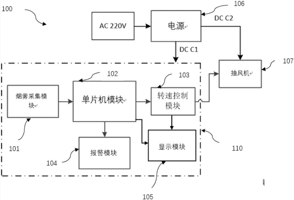
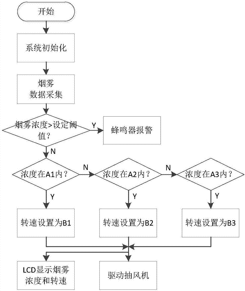
[0019] refer to figure 1 and figure 2 , this embodiment provides an electric soldering iron smoke removal system 100, including a power supply 106, an exhaust control module 110, and an exhaust fan 107;

[0020] The ventilation control module 110 further includes: a smoke collection module 101 , a single-chip microcomputer module 102 , a rotation speed control module 103 , an alarm module 104 and a display module 105 .

[0021] The power supply 106 is directly connected to the alternating current AC220V, which can convert the alternating current into direct current, and provide DC C1 to supply power to the exhaust control module 110 and DC C2 to supply power to the exhaust fan 107; in this embodiment, the power supply 106 can also be provided with a button switch, To make it convenient to turn off the power supply in advance when the power supply 106 is disconnected from the alternating current and prevent forgetting to unplug the power supply 106 so that the electric solder...

no. 2 example

[0037] This embodiment provides an electric soldering iron, which includes the electric soldering iron body and the electric soldering iron smoke removal system described in the first embodiment.

[0038] Compared with the prior art, the technical solution of the present invention has the following advantages:

[0039] The electric soldering iron smoke removal system uses a single-chip microcomputer module 102 to analyze the smoke concentration, and stores it in the single-chip microcomputer module 102 according to the set smoke concentration threshold value. When the set threshold value is exceeded, the single-chip microcomputer module 102 controls the alarm module to give an alarm. The single-chip microcomputer module 102 is set with a smoke concentration interval, and when the collected smoke concentration falls into the corresponding smoke interval, it will send information to the speed control module 103 to select an appropriate speed to drive the exhaust fan 107 to extrac...


PUM


Abstract

The invention provides an electric soldering iron smog removing system capable of automatically controlling an exhaust fan to operate. The electric soldering iron smog removing system comprises a power source, an exhaust control module and an exhaust fan. The electric soldering iron smog removing system is characterized in that the exhaust control module comprises a single-chip microcomputer module, the single-chip microcomputer module is connected with a smog gathering module and a revolving speed control module; the power source is connected with the exhaust control module and the exhaust fan, the exhaust fan is then connected to the exhaust control module. The operation of the exhaust fan can be controlled intelligently by the exhaust control module, when the smog is thin, the exhaust fan can be made to operate at a slow speed, and the waste of power resources caused by uninterrupted operation of the exhaust fan is reduced; and when the smog is thick, the exhaust fan can be controlled to operate at a high speed, and the smog can be removed timely and rapidly.

Description

technical field [0001] The invention relates to the field of welding technology, in particular to an electric soldering iron smoke removal system and the electric soldering iron. Background technique [0002] As people's consumption level is getting higher and higher, the public's demand for electronic products has increased significantly. However, in the process of production, testing and maintenance of electronic products, electric soldering irons are indispensable welding tools. During the soldering process with an electric soldering iron, a large amount of toxic and odorous fumes will be produced. These fumes will cause great harm to the human body after being inhaled, and when the smoke is large, it will block the technician's sight and cause operational errors. , poor welding and other technical problems. [0003] In order to eliminate this kind of smoke in the current market, the common smoke removal device is mainly a smoke device independent of the electric iron, w...

Claims


Application Information

Patent Timeline
Patent Type & Authority Applications(China)
IPC IPC(8): B23K3/08B23K3/03
CPCB23K3/03B23K3/08
Inventor 汪腾
Owner QUECLINK WIRELESS SOLUTIONS HF CO LTD
Learn More