
Non-momentum wheel satellite platform based on magnetic buoyancy device control system
A technology of control system and satellite platform, applied in the field of satellite platform, can solve the problems of high platform cost, high realization cost, friction, etc., and achieve the effect of high reliability, low cost and high precision
- Summary
- Abstract
- Description
- Claims
- Application Information
AI Technical Summary
Problems solved by technology
Method used
Image

Examples
Embodiment Construction
[0016] The preferred embodiments of the present invention are given below in conjunction with the accompanying drawings to describe the technical solution of the present invention in detail.
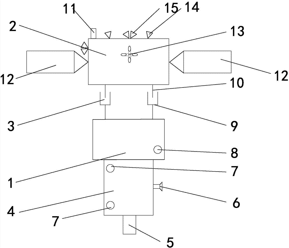
[0017] Such as figure 1 As shown, the present invention is based on the non-momentum wheel satellite platform of magnetic buoyancy device control system and comprises static cabin 1, dynamic cabin 2 and magnetic buoyancy device 3, and magnetic buoyancy device 3 is provided with a permanent magnet 9, static cabin 1 and magnetic buoyancy device 3 are connected through the dynamic cabin 2. The static cabin 1 includes the load cabin body 4, the payload base 5, the attitude sensor 6, the gyro sensor 7, and the platform electronics sensor 8. The load cabin body 4 is fixed at the bottom of the static cabin 1. A platform electronics sensor 8 is fixed on the cabin 1, two gyro sensors 7 are fixed on the surface of the load cabin body 4, an attitude sensor 6 is fixed on the right side of the load c...
PUM
 Abstract
Description
Claims
Application Information