Heat exchanger and heat exchange module

A technology of heat exchangers and heat exchange tubes, which is applied in the direction of indirect heat exchangers, heat exchanger types, heat exchanger shells, etc., can solve the problem that the heat exchanger space is not used effectively, and achieve convenient transportation and assembly The effect of simplicity, cost reduction, and increased heat exchange area

Active Publication Date: 2017-11-24
DANFOSS MICRO CHANNEL HEAT EXCHANGER JIAXING
View PDF8 Cites 5 Cited by
  • Summary
  • Abstract
  • Description
  • Claims
  • Application Information

AI Technical Summary

Problems solved by technology

In this way, a shielding plate (or metal plate) is still required to connect the two heat exchangers, resulting in the space between the two heat exchangers not being effectively used

Method used


Image

  • Heat exchanger and heat exchange module
  • Heat exchanger and heat exchange module
  • Heat exchanger and heat exchange module

Examples


Embodiment Construction

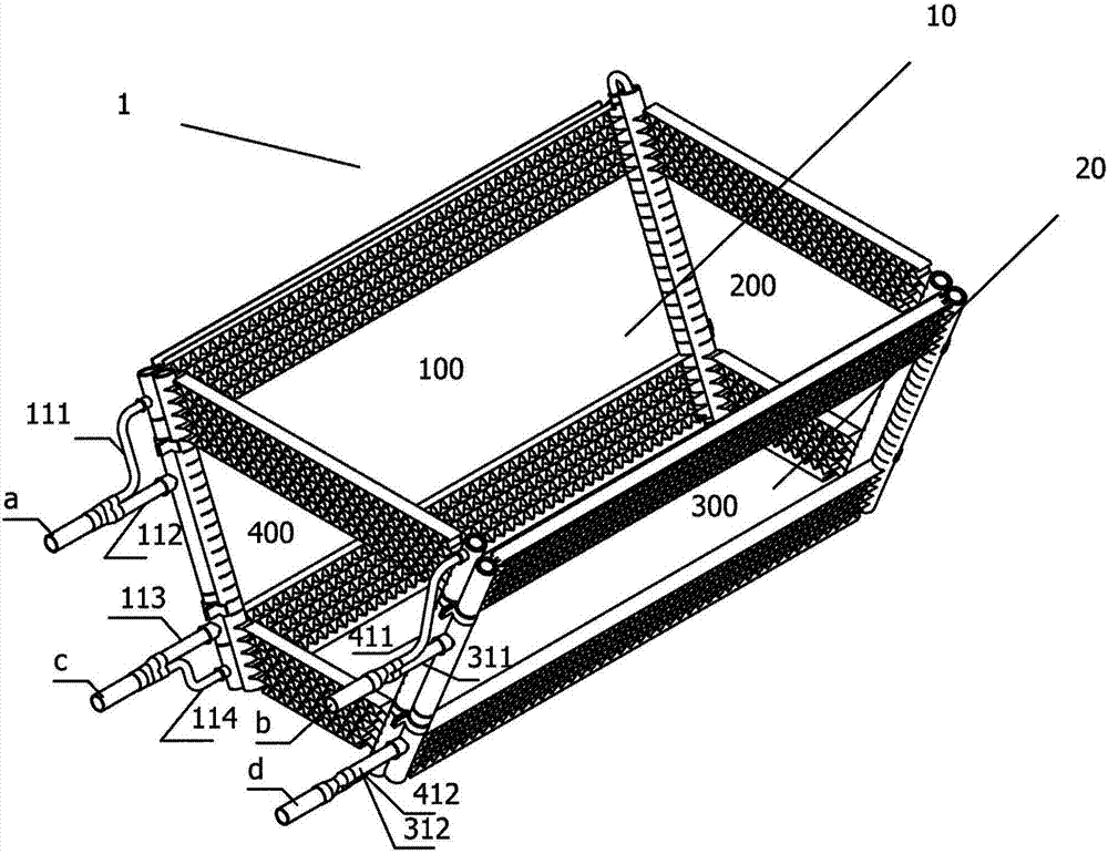
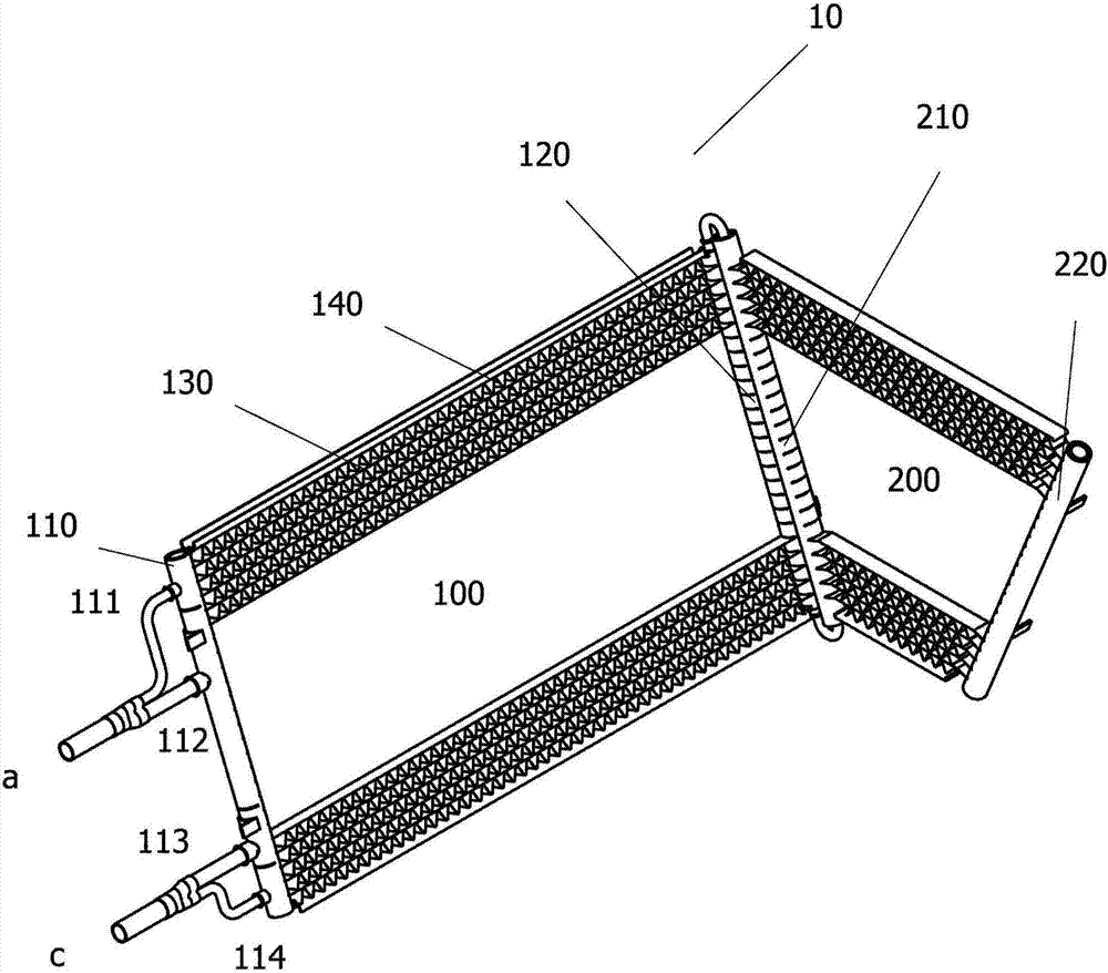
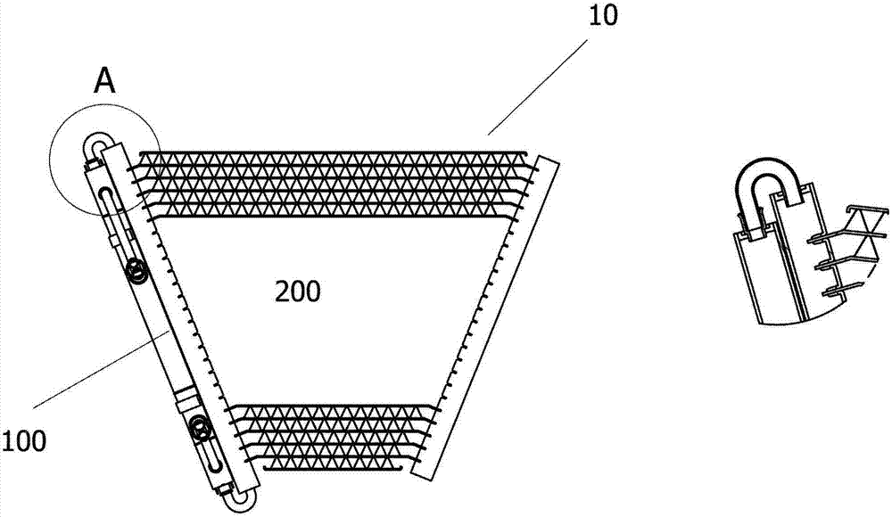
[0045] Below will pass embodiment, and in conjunction with appendix Figure 1-14, the technical solution of the present invention will be further specifically described. In the specification, the same or similar reference numerals designate the same or similar components. The following description of the embodiments of the present invention with reference to the accompanying drawings is intended to explain the general inventive concept of the present invention, but should not be construed as a limitation of the present invention.

[0046] It should be understood that the terms first, second, third, fourth, etc. used in the description are not intended to arrange related elements in sequence, but to distinguish related elements, and thus do not limit the present invention. The exemplary descriptions of side heat exchangers, main heat exchangers or rectangular heat exchangers and trapezoidal heat exchangers do not constitute limitations of the present invention, but description...


PUM


Abstract

The invention provides a heat exchanger. The heat exchanger comprises a first sub heat exchanger and a second sub heat exchanger, wherein the first sub heat exchanger is provided with a first flow collection pipe, a second flow collection pipe and at least two heat exchange pipes; the second sub heat exchanger is provided with a third flow collection pipe, a fourth flow collection pipe and at least one heat exchange pipe; and at least one heat exchange pipe in the first sub heat exchanger is one part of a flow path of the second sub heat exchanger.

Description

technical field [0001] The invention relates to the field of air conditioning, more specifically to a heat exchanger and a heat exchange module in the technical field of commercial air conditioning. Background technique [0002] The prior art document WO2011013672 discloses a heat source unit. Specifically, the heat source unit is provided with an air heat exchanger, and each air heat exchanger includes a plurality of cooling fins arranged at regular intervals, heat exchange tubes passing through the cooling fins, extending on both sides and in the same direction The bent bent sheet part and the heat exchange module. Each heat exchange module includes two air heat exchangers, each air heat exchanger having a bent portion disposed opposite to the bent portion of the other air heat exchanger. The air heat exchanger is inclined so that the lower edges are close to each other and the upper edges are spaced apart, whereby the heat exchange module is substantially V-shaped in si...

Claims


Application Information

Patent Timeline
Patent Type & Authority Applications(China)
IPC IPC(8): F25B39/00F24F13/30
CPCF24F13/30F25B39/00F28D1/04F28D1/0426F28D1/0417F28D2001/0273F28D1/05366F28D1/05375F28D2021/0068F28F9/262F28F9/0204F28F9/0243F24F1/18F28D1/05341F28F9/0219F28F9/0246F28F2009/0285F28D1/0443F28D1/05325F28D2001/0266
Inventor 金俊峰佩尔蒂埃·彼埃尔·奥利弗金欢
Owner DANFOSS MICRO CHANNEL HEAT EXCHANGER JIAXING
Why Eureka
Try Eureka