
Laser ring-down detection method

A detection method and ring-down technology, which is applied in the direction of color/spectral characteristic measurement, etc., can solve the problems that the laser ring-down detection method cannot accurately detect high-concentration gases, the detection accuracy cannot meet the precise gas measurement, and the concentration detection cannot be achieved, so as to avoid The ring down time is too short to overcome the limitation of the detection range and realize the effect of accurate detection

Active Publication Date: 2017-11-24
ACAD OF OPTO ELECTRONICS CHINESE ACAD OF SCI
View PDF8 Cites 1 Cited by
  • Summary
  • Abstract
  • Description
  • Claims
  • Application Information

AI Technical Summary

Problems solved by technology

[0003] When using the laser ring down detection method to detect gases with unknown concentrations in some specific occasions, although the detection accuracy of the laser ring down detection is high and very accurate detection results can be obtained, the laser ring down detection method is difficult due to its inherent characteristics. The detection range is limited
For example: Take the Picarro G2203 methane / acetylene analyzer as an example, its detection range is 0-20ppm, when the concentration of the gas to be detected is greater than the upper limit of the detection range, the laser ringdown detection cannot accurately measure the concentration of the gas to be measured detection
Therefore, in the field of high-concentration gas detection, infrared direct absorption detection technology is usually used for gas concentration detection. Although this technology has a large detection range, its detection accuracy cannot meet the needs of accurate measurement of certain gases.
[0004] Therefore, in the process of realizing the present invention, the inventor found that the laser ring down detection in the prior art has at least the defect that the detection range is limited, so that the laser ring down detection method cannot accurately detect high-concentration gases

Method used


Image

  • Laser ring-down detection method
  • Laser ring-down detection method
  • Laser ring-down detection method

Examples


Embodiment Construction

[0026] In order to make the object, technical solution and advantages of the present invention clearer, the present invention will be described in further detail below in conjunction with specific embodiments and with reference to the accompanying drawings.

[0027] It should be noted that all expressions using "first" and "second" in the embodiments of the present invention are to distinguish two entities with the same name but different parameters or parameters that are not the same, see "first" and "second" It is only for the convenience of expression, and should not be construed as a limitation on the embodiments of the present invention, which will not be described one by one in the subsequent embodiments.

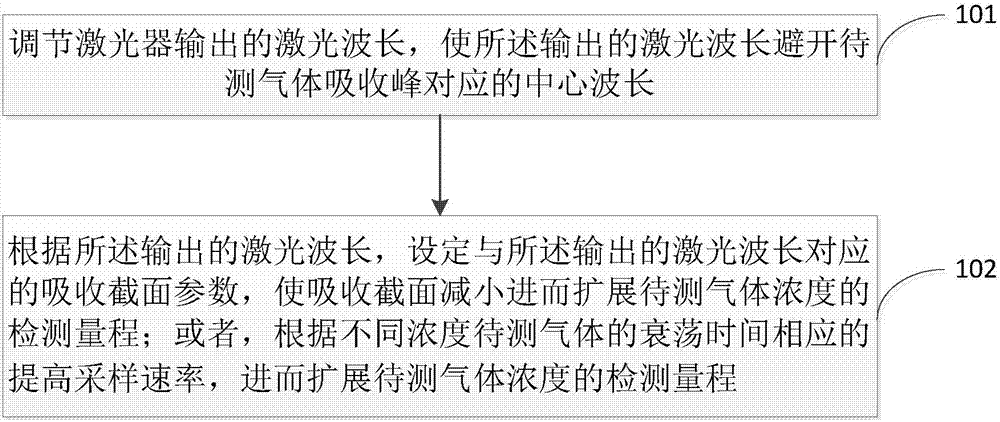
[0028] refer to figure 1 Shown is a flow chart of an embodiment of the laser ringdown detection method provided by the present invention. The laser ringdown detection method comprises:

[0029] Step 101, adjusting the laser wavelength output by the laser so that the...


PUM


Abstract

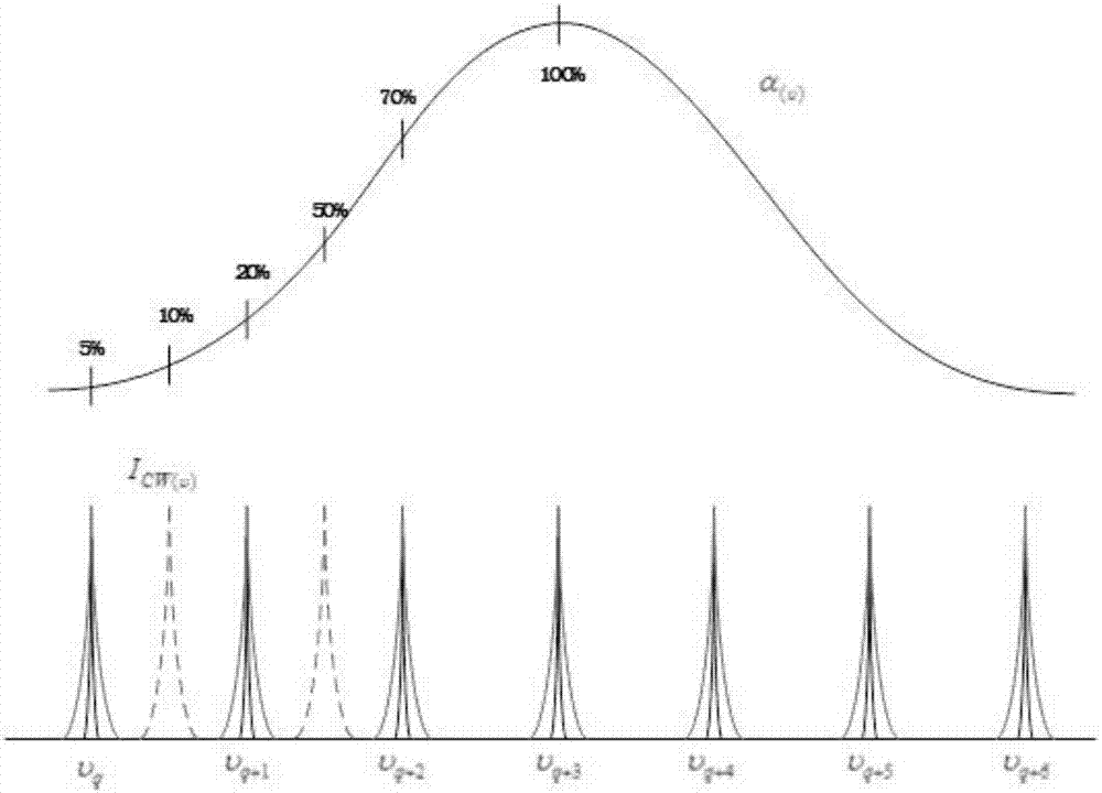
The invention discloses a laser ring-down detection method which comprises the following steps: laser wavelength output by a laser is regulated, so that the output laser wavelength avoids from a central wavelength corresponding to a to-be-detected gas absorption peak; absorption cross-section parameters corresponding to the output laser wavelength are set according to the output laser wavelength, so that the absorption cross-section is reduced to further expand the detection range of a to-be-detected gas concentration; or the sampling rate is correspondingly improved according to ring-down time of to-be-detected gases of different concentrations, and further the detection range of the to-be-detected gas concentration is expanded. According to the laser ring-down detection method disclosed by the invention, the defect in the prior art that the detection range is limited is overcome, the detection range of the laser ring-down detection is widened, and accurate detection of high-concentration gases is realized.

Description

technical field [0001] The invention relates to the technical field of gas concentration detection, in particular to a laser ring down detection method. Background technique [0002] Cavity ring-down spectroscopy (CRDS) technology is a laser absorption spectroscopy technology developed in the past 20 years. It has detection sensitivity and spectral selectivity comparable to gas chromatography and mass spectrometry. Moreover, CRDS The structure of the detection system is relatively simple, the response speed is fast, and the detection accuracy is high, which has attracted more and more attention and attention from the relevant detection fields. CRDS technology can be understood as an enhanced non-dispersive infrared absorption spectroscopy technology, which has an optical resonant cavity structure that increases the optical path of the laser through the absorbing material by several orders of magnitude. Therefore, the detection sensitivity also increases by the same order of ...

Claims


Application Information

Patent Timeline
Patent Type & Authority Applications(China)
IPC IPC(8): G01N21/39
CPCG01N21/39
Inventor 余锦貊泽强王金舵何建国
Owner ACAD OF OPTO ELECTRONICS CHINESE ACAD OF SCI
Learn More