
Bone conduction loudspeaker

A technology of bone conduction speaker and vibrating plate, which is applied in the direction of bone conduction transducer hearing equipment, sensors, sensor components, etc. It can solve the problems of not being able to protect one's privacy, affecting people around, and poor user experience, etc., to improve Experience, reduce vibration, reduce the effect of contact area

Inactive Publication Date: 2017-11-24
胡文
View PDF3 Cites 5 Cited by
  • Summary
  • Abstract
  • Description
  • Claims
  • Application Information

AI Technical Summary

Problems solved by technology

However, the existing bone conduction speaker will generate a resonance peak during use, which will resonate with the shell parts connected to the bone conduction speaker while vibrating, and a closed cavity is formed around the shell of the bone conduction speaker. The area of ​​the cavity is larger than that of the bone conduction speaker, which will amplify the vibration, and the amplified vibration will resonate with the air, which will cause sound leakage, which will lead to a very poor user experience
For example, when listening to music, the people around can hear it, which will affect the people around; or when answering the phone, the people around can also hear the voice of the other party, unable to protect their privacy

Method used


Image

  • Bone conduction loudspeaker
  • Bone conduction loudspeaker
  • Bone conduction loudspeaker

Examples


Embodiment 1

[0030] Such as Figure 4 , Figure 5 As shown, Figure 4 Is a schematic diagram of a three-dimensional structure of an embodiment of the present invention; Figure 5 for Figure 4 Top view. In this embodiment, the second vibrating plate 80 is provided with a number of hot-melt columns 81, and the hot-melt columns 81 and the housing 90 are thermally fused together to form a whole, so as to realize the connection between the second vibrating plate 80 and the housing 90. Form a closed cavity between.

[0031] In this embodiment, the second vibrating plate is hollowed out as much as possible, and different positions and areas of the second vibrating plate can be hollowed out according to actual needs. Reduce resonance and reduce external leakage. Since the second vibrating plate and the housing are thermally fused to form a whole and form a closed cavity, the second vibration plate objectively reduces the contact area between the entire bone conduction speaker and the housing, and c...

Embodiment 2

[0033] Such as Image 6 As shown, Image 6 It is a top view of another embodiment of the present invention. In this embodiment, the second vibrating plate 80 is fixed in the housing 90 by in-mold injection, which corresponds to forming a filling layer 91 between the second vibrating plate 80 and the housing 90. In this way, it can also be implemented in the first A closed cavity is formed between the two vibrating plates 80 and the housing 90.

[0034] Similarly, the second vibrating plate should be hollowed out as much as possible, and different positions and areas of the second vibrating plate can be hollowed out according to actual needs. Reduce resonance and reduce external leakage. Since the second vibration plate and the housing are fixed together by in-mold injection to form a closed cavity, the second vibration plate objectively reduces the contact area between the entire bone conduction speaker and the housing, and correspondingly reduces bone conduction. The leakage o...


PUM


Abstract

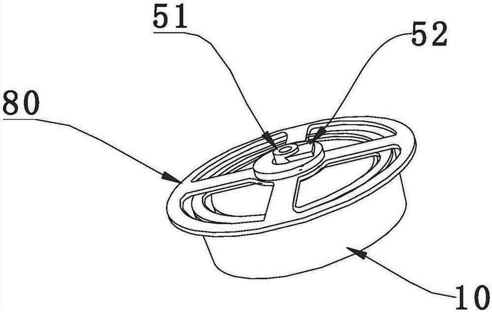
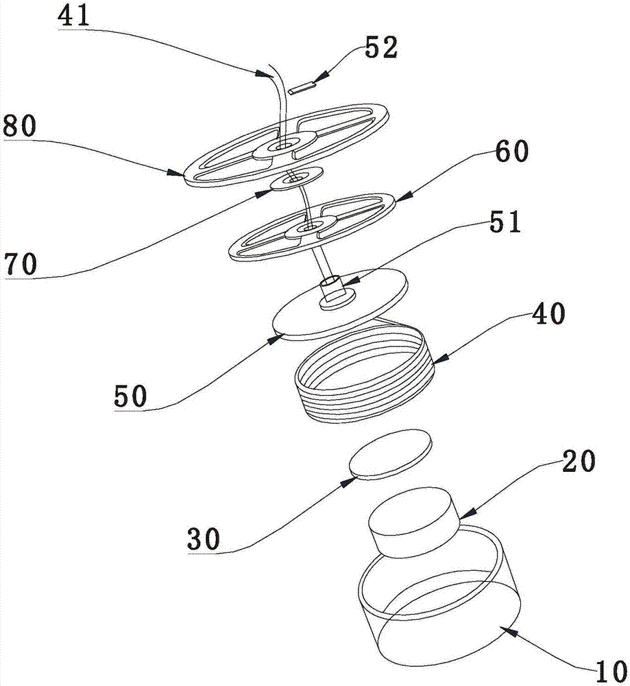
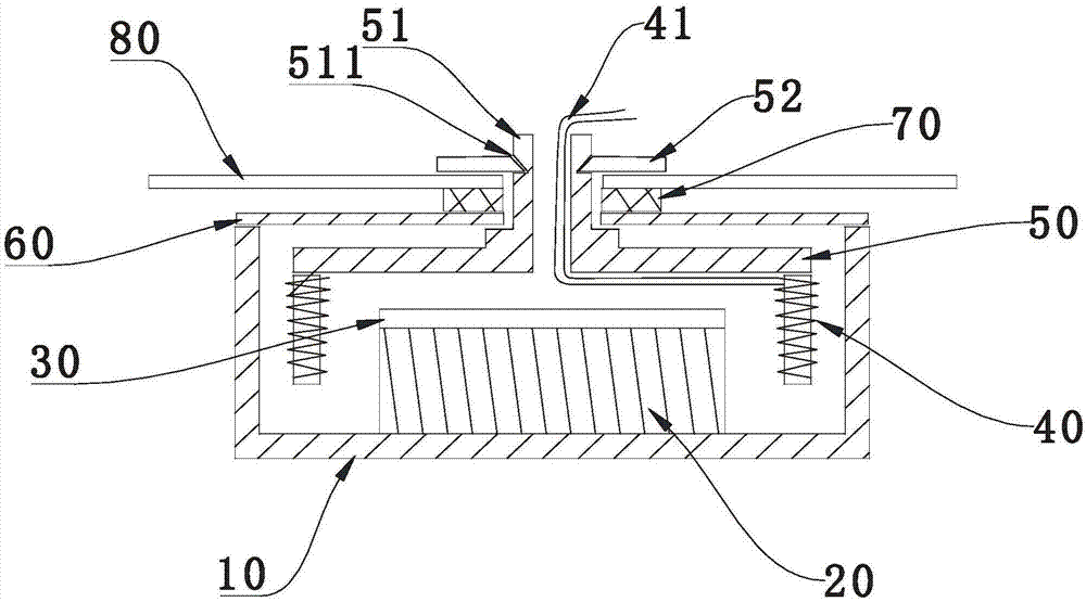
The invention provides a bone conduction loudspeaker which comprises a housing and a U-shaped iron fixedly mounted in the housing. A connecting frame is arranged in the U-shaped iron; a voice coil is fixedly mounted at the bottom of the connecting frame; a through hole cylinder is arranged at the center of the upper part of the connecting frame; a first vibrating reed and a second vibrating reed are inserted and fixedly mounted on the through hole cylinder; and a closed cavity is formed between the second vibrating reed and the housing. According to the bone conduction loudspeaker provided by the invention, two vibrating reeds are adopted, and a contact area of resonance is reduced, so that voice leakage is reduced. Compared to the prior art, when the bone conduction loudspeaker is worn, the vibratory sensation is reduced, so that the bone conduction loudspeaker is more comfortable to wear and experience of a user is effectively improved.

Description

Technical field [0001] The invention belongs to the technical field of electroacoustic products, and specifically relates to a double-vibrating plate bone conduction speaker capable of reducing external sound leakage. Background technique [0002] Bone conduction is a way of sound conduction, that is, by converting sound into mechanical vibrations of different frequencies, and transmitting sound waves through the human skull, bony labyrinth, inner ear lymphatic fluid, spiral organs, auditory nerve, and auditory center. Compared with the classic sound conduction method that generates sound waves through the diaphragm, bone conduction eliminates many steps of sound wave transmission, and can achieve clear sound reproduction in noisy environments, and sound waves will not be affected by diffusion in the air. others. [0003] The bone conduction speaker is a new type of electro-acoustic conversion device developed based on the sound conduction method of bone conduction. Because the bo...

Claims


Application Information

Patent Timeline
IPC IPC(8): H04R1/10H04R1/28
CPCH04R1/1091H04R1/2896H04R2460/13H04R2460/15
Inventor 胡文
Owner 胡文
Learn More