Mobile vehicle wireless charging system

A wireless charging and mobile technology, applied in electric vehicle charging technology, charging stations, electric vehicles, etc., can solve the problem of untimely charging

Active Publication Date: 2017-11-28
XJ POWER CO LTD +4
View PDF9 Cites 6 Cited by
  • Summary
  • Abstract
  • Description
  • Claims
  • Application Information

AI Technical Summary

Problems solved by technology

[0007] The purpose of the present invention is to provide a mobile vehicle charging system, which is used to solve the problems of untimely charging during the moving process in the system

Method used


Image

  • Mobile vehicle wireless charging system
  • Mobile vehicle wireless charging system
  • Mobile vehicle wireless charging system

Examples


Embodiment 1

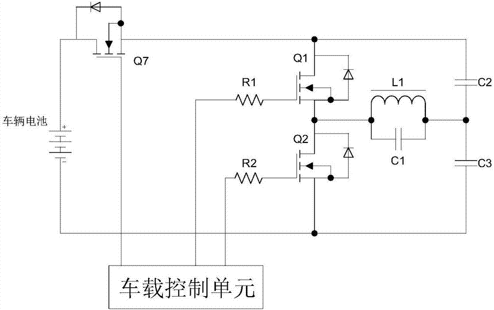
[0030] Vehicle transmitters such as figure 2 As shown: the positive pole of the vehicle battery is connected to the drain of the third switching tube Q7, the source of the third switching tube Q7 is connected to the drain of the first switching tube Q1 and one end of the capacitor C2, and the negative pole of the battery is connected to the second switching tube The source of Q2, one end of capacitor C3, and the other end of capacitor C2 are connected to the other end of capacitor C3, magnetic induction coil L1, and capacitor C1. The other end of magnetic induction coil L1 and capacitor C1 is connected to the source of the first switching tube Q1, the second The drains of the two switching tubes Q2 are connected, the gates of the first switching tube Q1 and the second switching tube Q2 are respectively connected to the driving resistors R1, R2, and the other ends of the driving resistors R1, R2 are connected to the vehicle control unit. The gate of the third switching tube Q7...

Embodiment 2

[0036] The vehicle-mounted transmitting device and the ground receiving device adopt infrared transmitting and receiving devices.

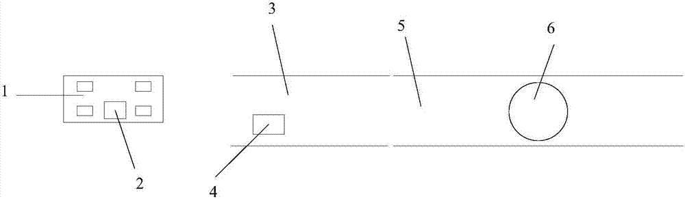
[0037] Install an infrared emitting device on the electric vehicle, and install an infrared receiving device at the starting position of the charging section. When the electric vehicle detects that the battery is in a power-depleted state and intends to enter the charging section where the energy transmitting coil is laid underground, the vehicle-mounted infrared transmitting device is manually turned on. When the vehicle drives to the starting position of the road section, the infrared receiving device on the ground receives the charging signal of the electric vehicle, and the acquisition circuit connected with the infrared receiving device transmits the signal to the ground control unit, and the ground control unit starts the energy emission laid underground in the charging road section The coil enters the pre-charging ready state.

[0038] Com...


PUM


Abstract

The invention provides a mobile vehicle wireless charging system. The system comprises a vehicle position detecting device composed of a vehicle-mounted wireless signal transmission module and a ground wireless signal receiving module, a resonance energy transmission circuit laid underground and a resonance vehicle-mounted energy receiving device; when an electric vehicle detects that a battery is in the electricity lack state, and wants to enter in the charging segment, a vehicle-mounted information transmission device is started and emits signals; when the ground signal receiving device receives the emitted signals, an energy transmission coil laid under the charging segment is started, and the pre-charging preparation state is executed. On the one hand, the problem that in the process of moving of the electric vehicle in the charging segment, charging preparation is slow is solved; on the other hand, the problem that the energy transmission coil is in the work state all the time, and energy losses are caused is solved.

Description

technical field [0001] The invention belongs to the technical field of wireless charging, and in particular relates to a wireless charging system for a mobile vehicle. Background technique [0002] Facing the increasingly severe pressure of energy conservation and emission reduction, the world automobile industry has entered a period of comprehensive transportation energy transformation. Green, clean and environmentally friendly energy has become a hot spot in the world today, and the development of electric vehicles has become the trend of clean energy development. Vigorously developing electric vehicles has become a clear direction for the governments of the United States, China, and many European countries to develop new energy vehicles, and the development of international electric vehicles has begun to accelerate. [0003] However, the charging problem is one of the important factors restricting the popularization, application and development of electric vehicles. At ...

Claims


Application Information

Patent Timeline
Patent Type & Authority Applications(China)
IPC IPC(8): B60L11/18
CPCB60L53/12B60L53/30B60L53/60Y02T10/70Y02T10/7072Y02T90/12Y02T90/14Y02T90/16
Inventor 张滨陈天锦曹亚曹智慧韩海伦张迎星周建华黄栋杰刘向立刘振威邓思维张晓丽张博
Owner XJ POWER CO LTD
Why Eureka
Try Eureka