Ultraviolet sterilization device

A sterilizing device and ultraviolet technology, which is applied to measuring devices, photometry, instruments, etc., can solve the problems of short life and rising operating costs

Inactive Publication Date: 2017-11-28
TOKUYAMA CORP
View PDF8 Cites 10 Cited by
  • Summary
  • Abstract
  • Description
  • Claims
  • Application Information

AI Technical Summary

Problems solved by technology

[0004] However, discharge tubes such as xenon flash lamps and low-pressure mercury lamps can radiate high-intensity ultraviolet rays, but due to their short lifespan, the discharge tubes need to be replaced periodically, resulting in increased operating costs.

Method used


Image

  • Ultraviolet sterilization device
  • Ultraviolet sterilization device
  • Ultraviolet sterilization device

Examples


Embodiment Construction

[0047] The above-mentioned actions and advantages of the present invention will be clarified from the modes for carrying out the invention described below. Hereinafter, embodiments of the present invention will be described with reference to the drawings. However, the present invention is not limited to these forms. In addition, in the drawings, some reference numerals may be omitted.

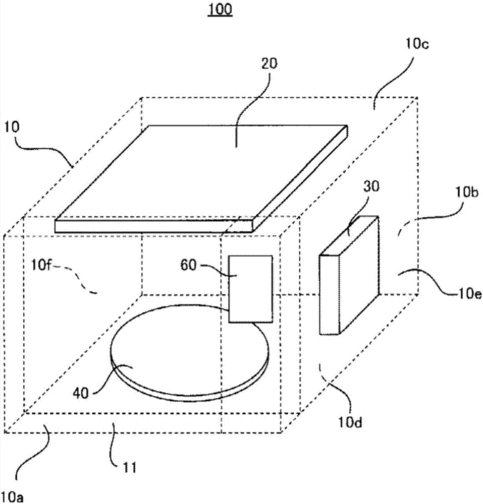
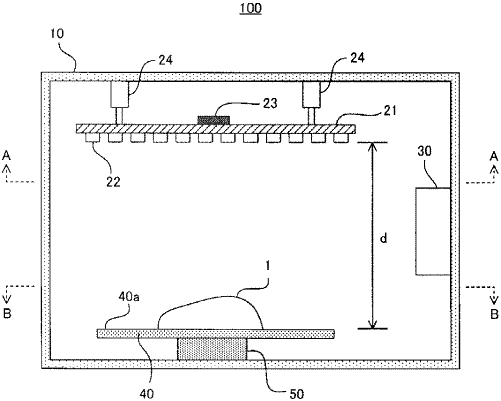
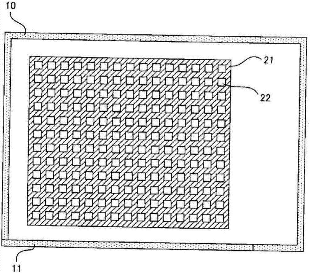
[0048] figure 1 It is a schematic perspective view schematically explaining the ultraviolet disinfection device 100 which concerns on one Embodiment of this invention, and is a figure which sees through the casing 10 (described later). figure 2 It is a cross-sectional view of the ultraviolet disinfection device 100 viewed from the front. The ultraviolet sterilizing device 100 has: a box-shaped housing 10, which has a front surface 10a, a rear surface 10b, an upper surface 10c, a bottom surface 10d, side surfaces 10e and 10f; a deep ultraviolet light source 20, which is arranged on the uppe...


PUM

PropertyMeasurementUnit
emission peakaaaaaaaaaa

Abstract

This ultraviolet sterilization device comprises: a deep-ultraviolet light source that has at least one deep-ultraviolet light-emitting diode and applies deep-ultraviolet light to an object to be sterilized; and a control means. The control means controls at least one selected from (1) an irradiation time t (unit: second) which is defined as the duration of application of deep-ultraviolet light to the object to be sterilized, (2) the distance d (unit: cm) between the object to be sterilized and the deep-ultraviolet light source, and (3) the light output P (unit: mW) of the deep-ultraviolet light source so that the cumulative dose I (unit: mJ / cm2) of deep-ultraviolet light to be applied to the object to be sterilized within the irradiation time is a predetermined value I0.

Description

technical field [0001] The invention relates to a sterilizing device using ultraviolet rays. Background technique [0002] Unlike sterilization using chemicals, ultraviolet sterilization has no residue, is highly safe, and hardly changes the irradiated object. Therefore, it is proposed to use ultraviolet light sterilization to sterilize objects in various scenarios. [0003] For example, Patent Document 1 describes a conveyor-type sterilizing device using a xenon flash lamp, which is characterized in that an ultraviolet irradiation chamber is provided at a middle position on the surface of the conveyor that transports the object to be sterilized by irradiation with ultraviolet rays. The entrance and exit of the irradiation chamber are connected to the upstream side light-shielding tube part and the downstream side light-shielding tube part with the surface of the conveyor as the bottom surface. In each of the above-mentioned light-shielding tube parts, it is used to make th...

Claims


Application Information

Patent Timeline
Patent Type & Authority Applications(China)
IPC IPC(8): A61L2/10H01L33/00
CPCA61L2202/11A61L2202/122A61L2/10A61L2202/14A61L2/26A61L2209/12G01J1/0252
Inventor 松井新吾
Owner TOKUYAMA CORP
Why Eureka
Try Eureka