Method for optimizing component type arrangement and device for optimizing component type arrangement

An optimization method and optimization technology, applied in the direction of electrical components, electrical components, configuration CAD, etc., to achieve the effects of shortening the work time for production change and adjustment, improving production efficiency, and minimizing assembly cycle time

Active Publication Date: 2020-06-05
FUJI KK
View PDF11 Cites 0 Cited by
  • Summary
  • Abstract
  • Description
  • Claims
  • Application Information

AI Technical Summary

Problems solved by technology

In this case, the production efficiency of the board varies depending on the arrangement order of the various component types

Method used


Image

  • Method for optimizing component type arrangement and device for optimizing component type arrangement
  • Method for optimizing component type arrangement and device for optimizing component type arrangement
  • Method for optimizing component type arrangement and device for optimizing component type arrangement

Examples


Embodiment Construction

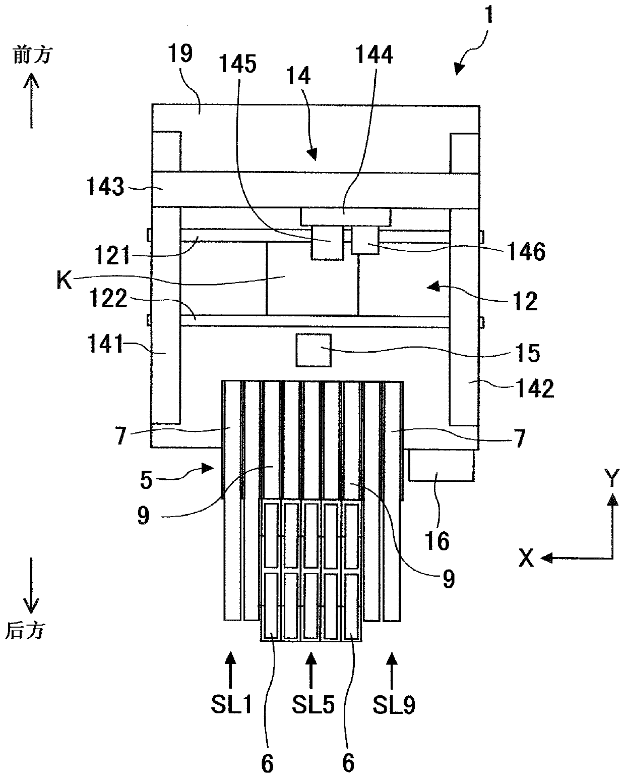
[0025] (1. Overall structure of the component mounting machine 1)

[0026] First, with figure 1 The overall structure of the component mounting machine 1 for performing the optimization method of component type arrangement according to the first and second embodiments of the present invention will be described for reference. figure 1 It is a top view schematically showing the overall structure of the component mounting machine 1 in a simplified manner. figure 1 The direction from the right side to the left side of the drawing is the X-axis direction of loading and unloading the substrate K, and the direction from the rear of the lower side of the drawing to the front of the upper side of the drawing is the Y-axis direction. The component mounting machine 1 is constituted by assembling a substrate transfer device 12 , a detachable manual feeder device 7 and an automatic feeder device 9 , a component transfer device 14 , a component camera 15 , and a control device 16 , etc., i...


PUM


Abstract

The present invention provides a method for optimizing the configuration of component types. The automatic feeder device (9) that automatically fills the component storage belts (85, 86) and the manual feeder device (7) that does not automatically fill When disposing the reel holding device (6) to the disposition positions (first to ninth slots SL1 to SL9) on the common tray (5), optimally dispose multiple component types (P1 to P9) in The method for optimizing the arrangement of the component types includes: determining a part (SL3-SL7) of the plurality of arrangement positions as a fixed position and fixing the automatic feeder device (S1); Under the condition that the automatic feeder device moves from a fixed position and the manual feeder device can be moved to any arrangement position other than the fixed position, the simulation of optimal arrangement of multiple component types at multiple arrangement positions is carried out The optimization step (S4). Thereby, the automatic feeder device can be effectively utilized, and the production efficiency can be improved by comprehensively considering the production change adjustment work time and the assembly cycle time.

Description

technical field [0001] The present invention relates to a component type layout method for optimally arranging a plurality of component types at a plurality of placement positions for the purpose of improving production efficiency when a feeder device is arranged at a plurality of placement positions arranged side by side on a component mounting machine Optimization method and optimization device. Background technique [0002] As equipment for producing substrates on which a plurality of components are mounted, there are solder printing machines, component mounting machines, reflow soldering machines, board inspection machines, and the like. Usually, these devices are connected to form a substrate production line. Among them, the component mounting machine includes a board transfer device, a component supply device, a component transfer device, and a control device. As a representative example of the component supply device, there is a feeder device of a system that draws ...

Claims


Application Information

Patent Timeline
Patent Type & Authority Patents(China)
IPC IPC(8): H05K13/02
CPCG06Q10/043G06Q50/04H05K13/0417H05K13/085H05K13/0857H05K13/086Y02P90/30G06F30/17G06F30/20G06F2111/06G06F2111/20
Inventor 杉本浩一朗本多利充
Owner FUJI KK
Why Eureka
Try Eureka