Overturning device for short-stress rolling mill

A technology of short stress rolling mill and turning device, applied in the direction of metal rolling stand, metal rolling mill stand, metal rolling, etc., to achieve the effect of high safety, simple structure and optimized structure

Active Publication Date: 2017-12-01
马鞍山市银鼎机械制造股份有限公司
View PDF7 Cites 2 Cited by
  • Summary
  • Abstract
  • Description
  • Claims
  • Application Information

AI Technical Summary

Problems solved by technology

The rolling mill turning device of the present invention has a simple and compact structure, and the whole device is light in weight, less in investment, easy to process and convenient to install, and can effectively solve the turning problem of the existing flat rolling mill through simple cooperation between a small number of parts, and the rolling mill Stable turning, high safety

Method used


Image

  • Overturning device for short-stress rolling mill
  • Overturning device for short-stress rolling mill
  • Overturning device for short-stress rolling mill

Examples


Embodiment 1

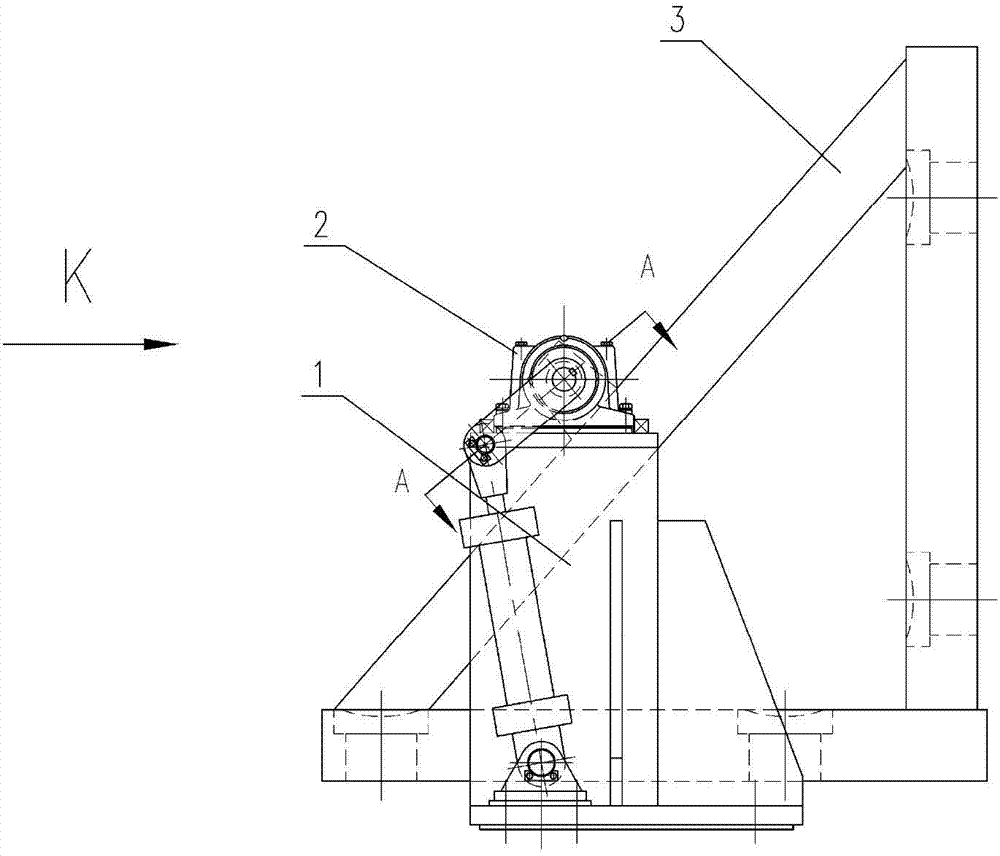
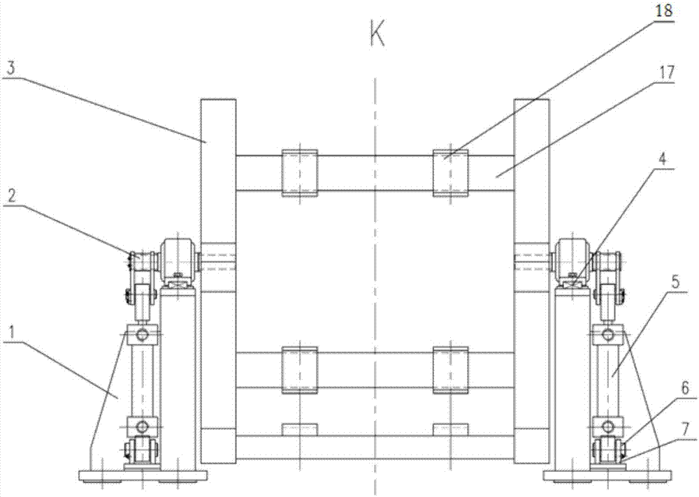
[0037] like figure 1 , figure 2 As shown, a short-stress rolling mill turnover device in this embodiment includes a fixed base 1, a transmission mechanism 2 and a turnover platform 3, wherein the fixed base 1 is symmetrically arranged on both sides of the turnover platform 3, and the Bolts are fixed on the civil foundation; the transmission mechanism 2 is symmetrically installed on the fixed base 1, and is fixedly connected with the turning platform 3, and the turning platform 3 is driven by the transmission mechanism 2 to turn over.

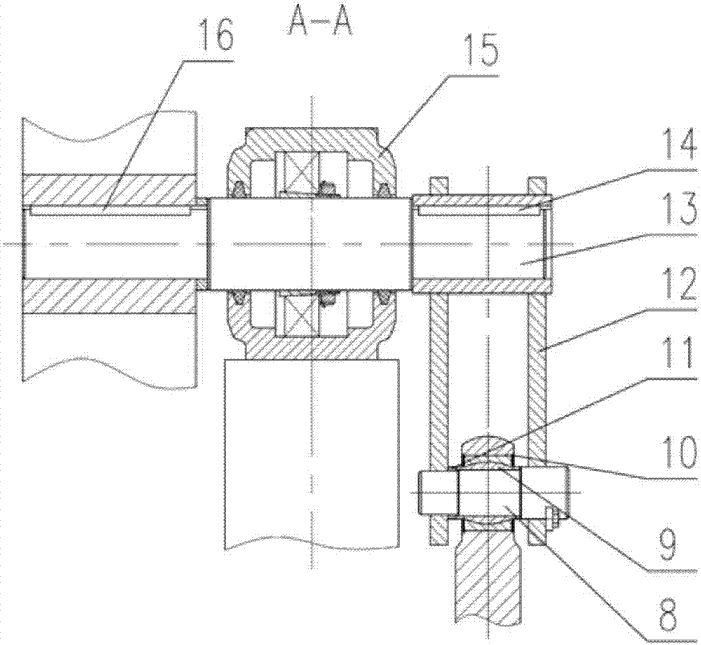
[0038] to combine figure 2 , image 3 The transmission mechanism 2 of this embodiment includes a hydraulic cylinder 5, a hydraulic cylinder base 7, a connecting rod 12, a transmission shaft 13 and a bearing seat 15, wherein the hydraulic cylinder base 7 is installed on the fixed base 1 by bolts, and the The hydraulic cylinder 5 is the tail earring type, and is connected with the hydraulic cylinder base 7 through the pin shaft I6. One end of ...

Embodiment 2

[0043] A kind of short-stress rolling mill turnover device of this embodiment, its structure is basically the same as embodiment 1, and its difference is: as Image 6 , Figure 7 As shown, in the present embodiment, two crossbeams 17 are connected between the horizontal right angle sides and the vertical right angle sides of the two triangular frames, wherein one crossbeam 17 is located at the junction center of the triangle frame right angle side and the hypotenuse, and the other A crossbeam 17 is located at one end close to the junction of two right-angled sides of the triangular frame, and each crossbeam 17 is correspondingly provided with two groups of pads: the third pad group 24 and the fourth pad group 25, and the spacing between the two groups of pads is different Specifically, in this embodiment, the distance between the third spacer group 24 is relatively large, and a larger rolling mill can be placed, and the distance between the fourth spacer group 25 is relatively...

Embodiment 3

[0047] A kind of short-stress rolling mill turnover device of this embodiment, its structure is basically the same as embodiment 1, and its difference is: as Figure 4 , Figure 5 As shown, the turning platform 3 of the present embodiment is horizontally provided with six crossbeams, and three crossbeams are respectively connected between the horizontal right-angled sides and the vertical right-angled sides of the two triangular frames, wherein, the first crossbeam 19 and the third crossbeam 21 There is a corresponding first pad set 22 on it, which is used to place a relatively large rolling mill. The second beam 20 and the third beam 21 are provided with a corresponding second pad set 23, which is used to place a relatively small rolling mill. rolling mill. Above-mentioned first crossbeam 19 is positioned at the intersection center of the right-angled side and the hypotenuse of triangular frame, and the third crossbeam 21 is positioned at an end close to the junction of two ...


PUM


Abstract

The invention discloses an overturning device for a short-stress rolling mill and belongs to the technical field of machine overturning. The overturning device comprises fixed bases, transmission mechanisms and overturning tables. The fixed bases are symmetrically arranged and are fixed to a civil engineering foundation through foundation bolts. The transmission devices are symmetrically arranged and are installed on the fixed bases. The overturning tables are connected with the transmission mechanisms through transmission shafts. Each transmission mechanism comprises a hydraulic cylinder, a hydraulic cylinder base, a connecting rod, a transmission shaft and a bearing seat. The hydraulic cylinders are installed on the fixed bases through the hydraulic cylinder bases. One ends of the connecting rods are connected with hydraulic cylinder flat heads, and the other ends of the connecting rods are connected with the transmission shafts. The transmission shafts are installed on the bearing seats and are fixedly connected with the overturning tables. The overturning device for the rolling mill is simple and compact in structure, the weight of the whole device is low, investment is little, machining is easy, installation is convenient, and due to simple cooperation among few parts, the overturning problem of an existing flat rolling mill is effectively solved.

Description

technical field [0001] The invention belongs to the technical field of mechanical overturning, and in particular relates to a short-stress rolling mill overturning machine. Background technique [0002] In the steel rolling production line, the rolling mills are generally arranged in a horizontal / vertical staggered manner. In order to save the operation time of roll changing, the flat / vertical rolling mills are assembled in the machine shop and directly hoisted to the operating side of the rolling line for complete machine replacement. In order to ensure the interchangeability of the flat rolling mill and the vertical rolling mill of the same model, the structure of the design is consistent, but the placement method is different when installed online. Among them, the vertical rolling mill is to turn the flat rolling mill 90 degrees. Due to the large size and weight of the rolling mill itself, it is impossible to turn over manually. Therefore, it is necessary to design a spe...

Claims


Application Information

Patent Timeline
Patent Type & Authority Applications(China)
IPC IPC(8): B21B31/14
CPCB21B31/14
Inventor 夏明星
Owner 马鞍山市银鼎机械制造股份有限公司
Why Eureka
Try Eureka