
Pneumatic hydraulic press

A gas-hydraulic and gas-liquid pressurization technology, applied in the direction of presses, stamping machines, mechanical equipment, etc., can solve the problems of explosion and use in places that cannot meet explosion-proof requirements, and achieve the effect of meeting explosion-proof requirements and pressure requirements

Inactive Publication Date: 2017-12-01
ROSS WUXI EQUIP COMPANY
View PDF8 Cites 0 Cited by
  • Summary
  • Abstract
  • Description
  • Claims
  • Application Information

AI Technical Summary

Problems solved by technology

[0002] The press is a common equipment in the workshop. The compaction or other operations of the material are completed by pressing down a pressure plate. It is relatively common to realize the drive of the pressure plate by a hydraulic cylinder. The common one is a motor-driven hydraulic pump. In the hydraulic Electric control valves and other components will also be installed on the oil circuit. In some occasions such as external high temperature, due to the existence of electrical components, there is a danger of explosion, so it cannot be used in places with explosion-proof requirements.

Method used


Image

  • Pneumatic hydraulic press
  • Pneumatic hydraulic press

Examples


Embodiment Construction

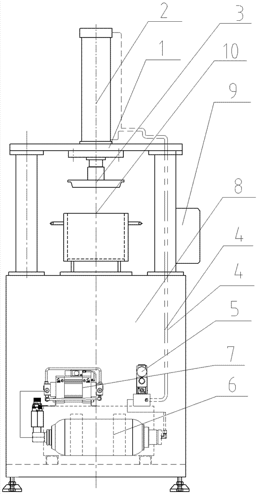
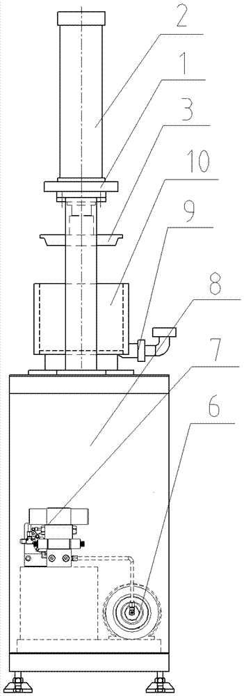
[0009] See figure 1 , figure 2 As shown, a gas-hydraulic machine includes a press frame 1, a hydraulic cylinder 2 arranged vertically downward is installed on the press frame 1, a pressure plate 3 is installed on the piston rod of the hydraulic cylinder 2, and the pressure plate 3 passes through the The oil pipe 4 and the air control reversing valve 5 are connected to one end of the accumulator 6, and the other end of the accumulator 6 is connected to the gas-liquid booster device 7; 7 are all arranged in the lower case 8, and the oil pipe 4 passes through the lower case 8 to connect to the hydraulic cylinder 2. 9 among the figure is the air control valve box connected with air control reversing valve 5. 10 among the figure is container.


PUM


Abstract

The invention relates to the field of press equipment, in particular to a pneumatic hydraulic press capable of effectively meeting the pressure requirement and simultaneously meeting the explosion prevention requirement. The pneumatic hydraulic press comprises a press frame, wherein a vertically downward hydraulic cylinder is mounted on the press frame; a pressure plate is mounted on a piston rod of the hydraulic cylinder; the pneumatic hydraulic press is characterized in that the pressure plate is connected with one end of an energy accumulator through an oil pipe and a pneumatic operated directional valve; and the other end of the energy accumulator is connected with a pneumatic hydraulic pressurizing device.

Description

technical field [0001] The invention relates to the field of press equipment, in particular to a pneumatic hydraulic press. Background technique [0002] The press is a common equipment in the workshop. The compaction or other operations of the material are completed by pressing down a pressure plate. It is relatively common to realize the drive of the pressure plate by a hydraulic cylinder. The common one is a motor-driven hydraulic pump. In the hydraulic Electric control valves and other components will also be installed on the oil circuit. In some occasions such as external high temperature, due to the existence of electrical components, there is a danger of explosion, so it cannot be used in places with explosion-proof requirements. Contents of the invention [0003] In order to solve the above problems, the present invention provides a gas-hydraulic machine, which can effectively meet the pressure requirements and meet the explosion-proof requirements. [0004] Its t...

Claims


Application Information

Patent Timeline
Patent Type & Authority Applications(China)
IPC IPC(8): B30B1/32F15B1/02
CPCF15B1/02B30B1/32
Inventor 朱宏亮王士永
Owner ROSS WUXI EQUIP COMPANY
Learn More