
Pressure calibration method of bipolar guide rail pressure mechanism

A technology of pressure mechanism and calibration method, which is applied in the direction of force/torque/work measuring instrument calibration/test, measuring device, instrument, etc., can solve the problems of increased scrap rate, enterprise loss, damage to tube and shell, etc. The effect of stress demand reduction

Inactive Publication Date: 2020-08-04
山西斯米咖科技有限公司
View PDF10 Cites 0 Cited by
  • Summary
  • Abstract
  • Description
  • Claims
  • Application Information

AI Technical Summary

Problems solved by technology

[0002] In the gas-tight resistance welding of the shell, it is very important to control the pressure applied to the shell, especially in the welding of the ceramic shell, the shell will be damaged if the pressure is too large, the scrap rate will increase, and it will bring great harm to the enterprise. loss, the current method is to control the pressure only by the experience of skilled workers, there is no scientific and reasonable method

Method used


Image

  • Pressure calibration method of bipolar guide rail pressure mechanism

Examples


Embodiment 1

[0018] The pressure calibration method of the bipolar rail pressure mechanism is carried out according to the following steps:

[0019] a. Install the pressure sensor on the index plate of the shell positioning mechanism;

[0020] b. Start the motor, drive the Z-axis screw shaft to rotate through the coupling, the Z-axis screw shaft drives the Z-axis nut block to go down, and the Z-axis nut block drives the sealing head to go down. When the photoelectric sensor on the pressure block will seal and weld When the photoelectric sensor on the head is blocked, it is set as the initial calibration point;

[0021] c. Slowly apply pressure, the incremental value of the sealing head moving down is 0.001mm--0.1mm, and record the pressure values ​​of the pressure sensor as 500g, 700g, 900g, 1100g, 1300g, 1500g, 1700g, 1900g, 2100g, 2300g When the displacement value of the corresponding welding head is repeated twice, the average value of the three times of data is taken respectively to o...

Embodiment 2

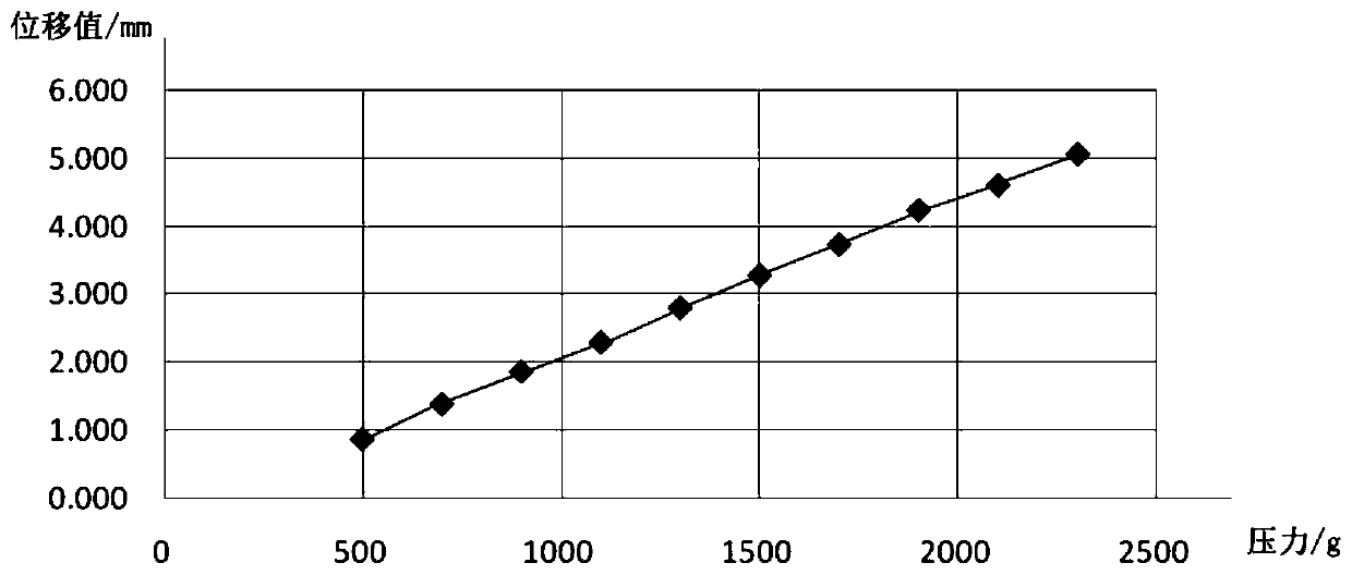
[0024] As shown in Table 1, in order to facilitate understanding, the following data examples are selected on the basis of Embodiment 1 for illustration:

[0025] pressure (g) First time / (mm) Second time / (mm) The third time / (mm) Displacement value / (mm) 500 0.900 0.850 0.900 0.883 700 1.390 1.410 1.410 1.403 900 1.890 1.860 1.880 1.877 1100 2.270 2.320 2.330 2.307 1300 2.814 2.820 2.810 2.815 1500 3.216 3.340 3.330 3.295 1700 3.686 3.780 3.780 3.749 1900 4.196 4.280 4.280 4.252 2100 4.616 4.616 4.630 4.621 2300 5.036 5.110 5.080 5.075

[0026] Such as figure 1 As shown, according to Table 1, the displacement value is used as the abscissa and the pressure value is the y-coordinate to draw a line graph of the displacement value and the pressure value. According to the line graph, it can be seen that the relationship between the displacement value and the pressure value is: F=kx+b,...


PUM


Abstract

The invention discloses a pressure calibration method of a bipolar guide rail pressure mechanism. The pressure calibration method comprises the following steps: a pressure sensor is installed on an index plate of a tube housing positioning mechanism; and a motor is started, a Z-axis lead screw shaft is driven to rotate through a shaft coupler, the Z-axis lead screw shaft drives a Z-axis nut blockto move downwards, the Z-axis nut block drives a seal welding head to move downwards, and when the photoelectric sensor on the seal welding head is shielded by a photoelectric induction piece on a pressure block, a starting calibration point is set. The method is simple, convenient and precise, and the rejection rate is reduced while the pressure requirements of various common environments are met.

Description

technical field [0001] The invention belongs to the technical field of airtight resistance welding pressure calibration, and in particular relates to a pressure calibration method of a bipolar guide rail pressure mechanism. Background technique [0002] In the gas-tight resistance welding of the shell, it is very important to control the pressure applied to the shell, especially in the welding of the ceramic shell, the shell will be damaged if the pressure is too large, the scrap rate will increase, and it will bring great harm to the enterprise. Loss, the current method is to control the pressure only by the experience of skilled workers, there is no scientific and reasonable method. Contents of the invention [0003] In order to overcome the defects of the prior art, the purpose of the present invention is to provide a simple, convenient and precise pressure calibration method of the bipolar guide rail pressure mechanism, which can meet the pressure requirements of vario...

Claims


Application Information

Patent Timeline
Patent Type & Authority Applications(China)
IPC IPC(8): G01L25/00
CPCG01L25/00
Inventor 任思岩杨凯骏尹卫东
Owner 山西斯米咖科技有限公司
Learn More