
A chemical erosion peeling machine

A chemical erosion and peeling machine technology, applied in the field of metal bar processing equipment, can solve the company's high tool purchase costs and work injury compensation, high operating costs, short tool life and other problems, to achieve shortened maintenance time, cutting force The effect of reducing and prolonging the service life

Active Publication Date: 2019-11-01
TAICANG BEST MECHANICAL EQUIP
View PDF5 Cites 0 Cited by
  • Summary
  • Abstract
  • Description
  • Claims
  • Application Information

AI Technical Summary

Problems solved by technology

[0005] 1. Most of the current peeling machines do not pretreat the bar material. The high surface hardness of the bar material causes the tool to wear quickly and needs to be replaced frequently. It may even break the knife, which threatens the lives of workers. The company has to bear the high cost of tool purchase Fees and Workers' Compensation
[0006] 2. Most of the current peeling machines do not cool the processing parts. The tool generates heat accumulation, which is prone to blunt and broken knives. The service life of the tool is short, and it will threaten the lives of workers, and the operating cost of the enterprise is high.

Method used


Image

  • A chemical erosion peeling machine
  • A chemical erosion peeling machine
  • A chemical erosion peeling machine

Examples


Embodiment 1

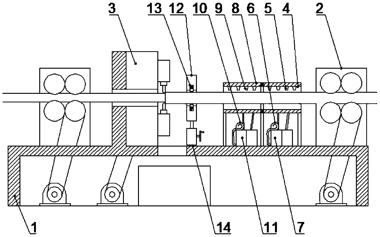
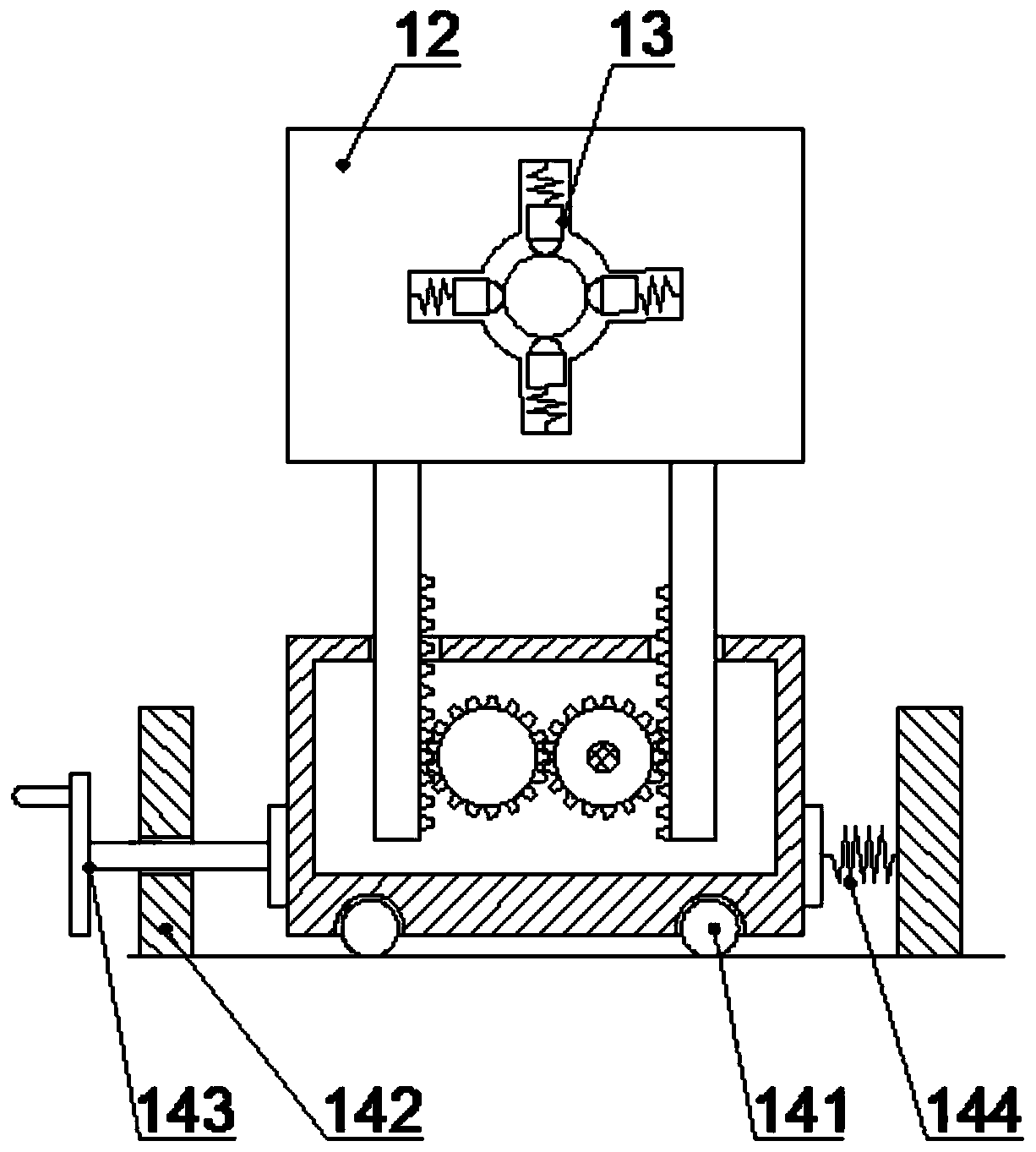
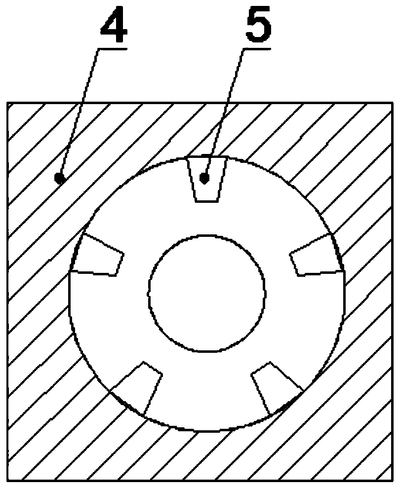
[0050] Such as figure 1 A chemical erosion peeling machine shown includes: a frame 1, a feed support mechanism 2, a reaction mechanism, a cleaning and cooling mechanism, a positioning mechanism, and a peeling mechanism 3, and the feed support mechanism 2 is arranged on both sides of the frame 1 , the frame 1 is sequentially provided with a reaction mechanism, a cleaning and cooling mechanism, a positioning mechanism and a peeling mechanism 3; the reaction mechanism includes a reaction chamber 4, a reagent nozzle 5, a liquid pump 6 and a storage box 7, and the reagent nozzle 5 is arranged inside the reaction chamber 4, a material storage box 7 is arranged below the reaction chamber 4, a liquid pump 6 is arranged on the material storage box 7, and the liquid pump 6 is connected to the liquid outlet of the material storage box 7, so that The reagent nozzle 5 is connected to the liquid pump 6 through a pipeline, and the storage tank 7 is connected to the bottom of the reaction cha...

Embodiment 2

[0059] Such as figure 2 A chemical erosion peeling machine shown includes: a frame 1, a feed support mechanism 2, a reaction mechanism, a cleaning and cooling mechanism, a positioning mechanism, and a peeling mechanism 3, and the feed support mechanism 2 is arranged on both sides of the frame 1 , the frame 1 is sequentially provided with a reaction mechanism, a cleaning and cooling mechanism, a positioning mechanism and a peeling mechanism 3; the reaction mechanism includes a reaction chamber 4, a reagent nozzle 5, a liquid pump 6 and a storage box 7, and the reagent nozzle 5 is arranged inside the reaction chamber 4, a material storage box 7 is arranged below the reaction chamber 4, a liquid pump 6 is arranged on the material storage box 7, and the liquid pump 6 is connected to the liquid outlet of the material storage box 7, so that The reagent nozzle 5 is connected to the liquid pump 6 through a pipeline, and the storage tank 7 is connected to the bottom of the reaction ch...

Embodiment 3

[0063] Such as image 3 A chemical erosion peeling machine shown includes: a frame 1, a feed support mechanism 2, a reaction mechanism, a cleaning and cooling mechanism, a positioning mechanism, and a peeling mechanism 3, and the feed support mechanism 2 is arranged on both sides of the frame 1 , the frame 1 is sequentially provided with a reaction mechanism, a cleaning and cooling mechanism, a positioning mechanism and a peeling mechanism 3; the reaction mechanism includes a reaction chamber 4, a reagent nozzle 5, a liquid pump 6 and a storage box 7, and the reagent nozzle 5 is arranged inside the reaction chamber 4, a material storage box 7 is arranged below the reaction chamber 4, a liquid pump 6 is arranged on the material storage box 7, and the liquid pump 6 is connected to the liquid outlet of the material storage box 7, so that The reagent nozzle 5 is connected to the liquid pump 6 through a pipeline, and the storage tank 7 is connected to the bottom of the reaction cha...


PUM


Abstract

The invention discloses a chemical erosion peeling machine which comprises a rack, feeding supporting mechanisms, a reaction mechanism, a cleaning cooling mechanism, a positioning mechanism and a peeling mechanism. The feeding supporting mechanisms are arranged on the two sides of the rack. The reaction mechanism, the cleaning cooling mechanism, the positioning mechanism and the peeling mechanism are sequentially arranged on the rack. The reaction mechanism comprises a reaction cavity, a reagent nozzle, a liquid pump and a material storage box. The reagent nozzle is arranged in the reaction cavity. The material storage box is arranged below the reaction cavity. The liquid pump is arranged on the liquid storage box and is connected with a liquid outlet of the liquid storage box. The reagent nozzle is connected with the liquid pump through a pipeline. The liquid storage box is connected with the bottom of the reaction cavity through a pipeline. The chemical erosion peeling machine can conduct pretreatment on the bar, abrasion of a tool is reduced, the phenomenon that the tool is broken and injures people is avoided, the service life of the tool is prolonged, the chemical erosion peeling machine can clean the surface of the bar, the tool can be cooled, accumulation of heat energy of the tool is prevented, and the service life of the tool is prolonged.

Description

technical field [0001] The invention belongs to the field of metal bar processing equipment, in particular to a chemical erosion peeling machine. Background technique [0002] With the development of my country's manufacturing industry, the processing requirements for various metal materials are getting higher and higher. However, the metal bars produced by casting and hot rolling have irregular shapes and dimensions that do not meet the tolerance requirements, especially aluminum bars. , Its surface has a layer of oxide film, and the metal bar must be peeled by a peeling machine to remove its surface defects before it can be used normally. Therefore, the importance of the peeling machine is self-evident. [0003] During the peeling process, due to the high hardness and unevenness of the shell of the metal bar, the damage to the tool is great, and it needs to be replaced frequently, and the knife may break, which may hurt the workers. The company needs to bear high costs. To...

Claims


Application Information

Patent Timeline
Patent Type & Authority Patents(China)
IPC IPC(8): C23F1/08C23G3/00
CPCC23F1/08C23G3/00
Inventor 刘彦付陈伟勇
Owner TAICANG BEST MECHANICAL EQUIP
Learn More