Drawing machine for textile fiber strips

A technology for fiber strips and cans, used in spinning machines, textiles and papermaking, drafting equipment, etc.

Active Publication Date: 2017-12-01
TRUETZSCHLER GRP SE
View PDF8 Cites 2 Cited by
  • Summary
  • Abstract
  • Description
  • Claims
  • Application Information

AI Technical Summary

Problems solved by technology

Furthermore, considering points such as the transport capacity of the individual drawframes weighing about 1.5 tons (t), it is basically impossible to increase the can size of the drawframe for known methods for filling smaller, Simple dimensioning of drawing frames such as cans with a diameter of 1000 millimeters (mm)

Method used


Image

  • Drawing machine for textile fiber strips
  • Drawing machine for textile fiber strips
  • Drawing machine for textile fiber strips

Examples


Embodiment Construction

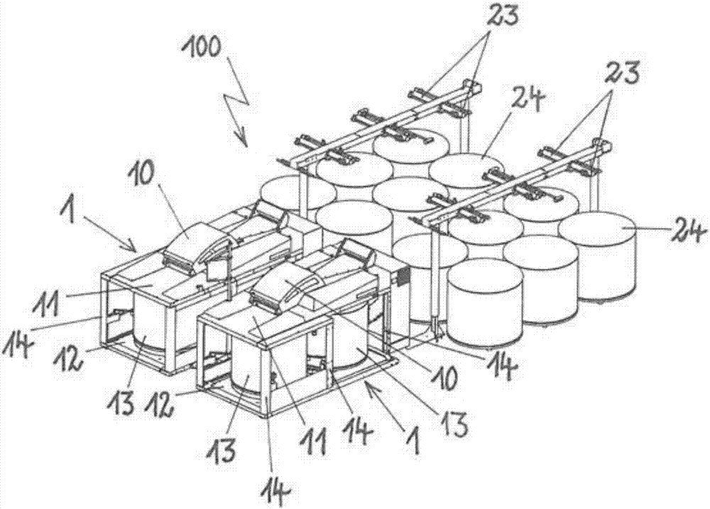
[0025] figure 1 A perspective view shows a draw frame 100 , which is designed as a double-head draw frame and includes two draw frames 1 . Arranged upstream of the two drawing frames 1 is a creel 23 of the creel arrangement, which guides the woven fiber sliver, not shown in detail, from the can 24 and feeds it to the drawing frame 1 . The woven sliver enters the drafting system 10 in which a plurality of slivers (six slivers from six cans 24 of each drawing frame 1 in the illustrated embodiment) They are placed side by side, and these fiber slivers are drawn into new, single fiber slivers, for example having the same cross-section as the respective fiber slivers from the can 24 . The example shows six cans 24 per drawing frame 1 and each can 24 preferably likewise has a diameter of 1200 mm.

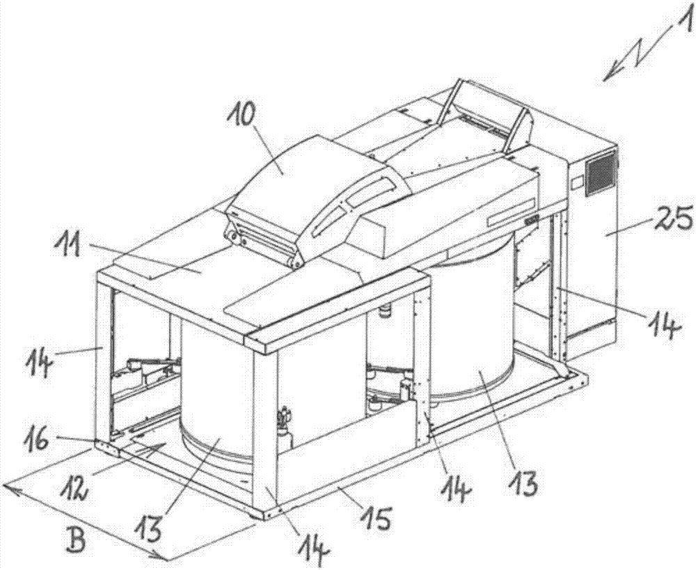
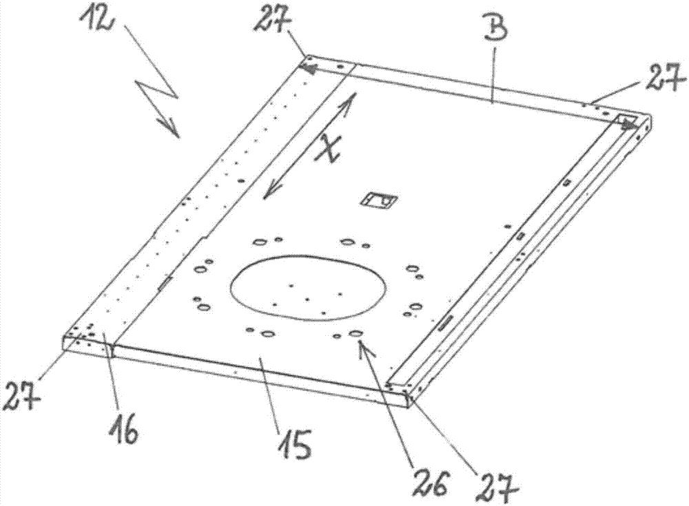
[0026] The drawing frame 1 has a basic structure consisting of a coil housing 11 on which the drafting system 10 is accommodated. On the underside there is a base plate 12 , and the co...


PUM

PropertyMeasurementUnit
diameteraaaaaaaaaa
diameteraaaaaaaaaa
widthaaaaaaaaaa

Abstract

A drawing frame (1) for textile fiber strips has a drafting system (10) received on a loop casing (11) and a base plate (12) on which the at least one ring strip cylinder(13) is supported. The coil housing (11) is arranged on the base plate (12) at intervals by means of struts (14). The base plate ( 12 ) has a main board ( 15 ) and side plates ( 16 ) such that the base plate ( 12 ) has a width (B) capable of withstanding at least one ring strip cylinder(13) having a diameter of 1200 mm on the width. In a drawing machine ( 100 ) having a first drawing device (1) and a second drawing device (1) according to the structure described above, the side plates (16) are so arranged on the main board (15) that the side plates (16) correspondingly point to adjacent drawing devices (1) .

Description

technical field [0001] The invention relates to a drawing frame for textile fiber slivers, which has a drafting system mounted on a coil housing and has a base plate on which at least one coil can can be mounted rotatably, And wherein, the coil cans are arranged at intervals on the bottom plate by means of pillars. Background technique [0002] The drawing frame device can be used to draw in individual fiber slivers from a plurality of cans via a so-called creel arrangement with creels assigned to the cans, lay them side by side, draft and then splice them into new ones. , a single fiber sliver, preferably having the same cross-sectional dimension as each fiber sliver of each drawn-in plurality of fiber slivers. Feed creel or driven creel rollers are used for drawing in the fiber sliver and several individual cans can be arranged upstream from which the fiber sliver is taken out in order to increase the throughput of the draw frame . [0003] In order to further increase ...

Claims


Application Information

Patent Timeline
Patent Type & Authority Applications(China)
IPC IPC(8): D01H5/18D01H5/16D01H5/00
Inventor 布莉塔·卢思特海腾托马斯·施密茨
Owner TRUETZSCHLER GRP SE
Why Eureka
Try Eureka