Roadbed compaction degree detecting device

A detection device and technology of compaction degree, which are applied in the field of foundation soil survey, infrastructure engineering, construction, etc., can solve the problem of inconvenient soil sample collection, inaccurate test results of roadbed compaction degree, extension of roadbed and pavement engineering use. Life and other issues, to achieve the effect of reducing the forward resistance

Active Publication Date: 2017-12-01
CHINA MCC5 GROUP CORP
View PDF6 Cites 6 Cited by
  • Summary
  • Abstract
  • Description
  • Claims
  • Application Information

AI Technical Summary

Problems solved by technology

In view of the prior art, in the process of testing the compaction degree of high-fill subgrade, it is inconvenient to collect soil samples of each compacted layer, that is, it is easy to mix the soil samples in each compacted layer, which leads to the detection of subgrade compaction degree. The result is inaccurate, resulting in the problem that the strength and stiffness of the subgrade and pavement engineering do not meet the relevant standards. The applicant designed a device for testing the compactness of different compacted layers to ensure the accuracy of sampling and ensure the compactness of the subgrade. It actually conforms to the relevant construction requirements, and then achieves the purpose of prolonging the service life of the subgrade and pavement engineering;

Method used


Image

  • Roadbed compaction degree detecting device
  • Roadbed compaction degree detecting device
  • Roadbed compaction degree detecting device

Examples


Embodiment 1

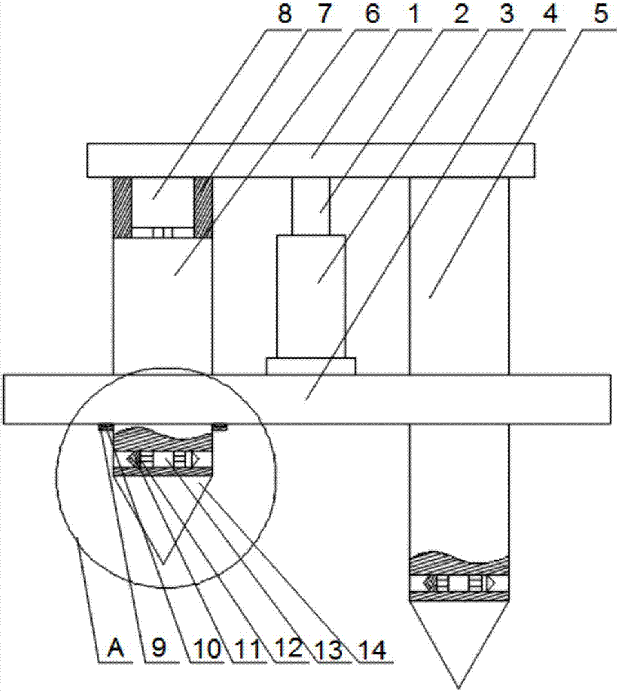
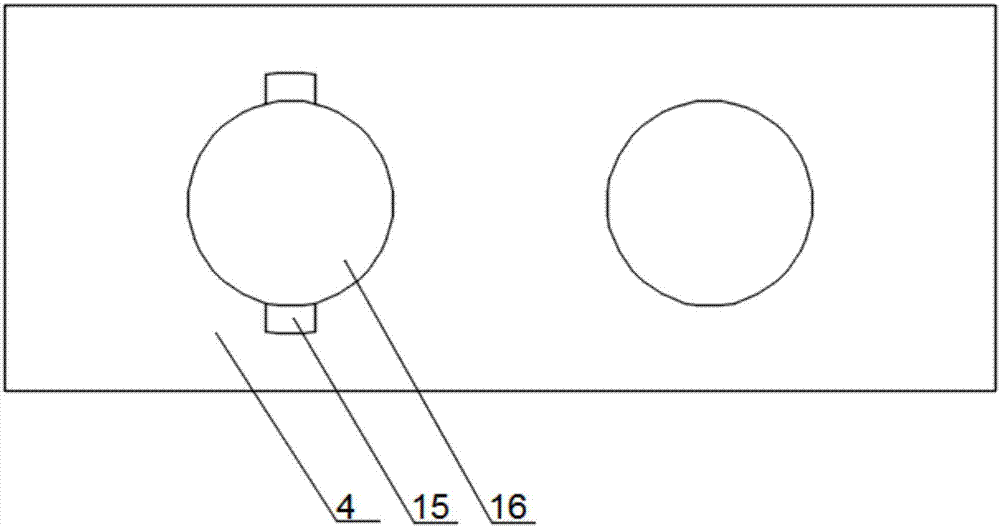
[0025] Such as Figure 1~3As shown, the present embodiment includes a base plate 3 and a hydraulic cylinder 3 vertically arranged on the upper surface of the base plate 3. On the output end of the hydraulic cylinder 3, a lower pressing plate 1 parallel to the base plate 3 is fixed. On the lower surface of the lower pressing plate 1 One end is fixed with a long column 5, and the other end of the lower surface of the lower platen 1 is provided with a fixed cylinder 7. The motor 8 is installed in the fixed cylinder 7, and the output end of the motor 8 is connected with a short column 6 parallel to the long column 5. Two through holes 15 are respectively opened on the bottom plate 3, and the two through holes 15 are respectively centered with the long column 5 and the short column 6, and the long column 5 and the short column 6 pass through the through hole 15 respectively and then move toward the vertical direction. Extending away from the direction of the lower surface of the bo...

Embodiment 2

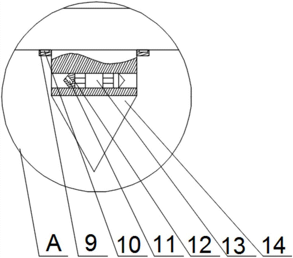
[0030] Such as Figure 1~3 As shown, the longitudinal section of the driving head 12 in this embodiment is an acute triangle, and the plane where the long side of the driving head 12 is located is connected to the output end of the two-way cylinder 13, and the blind hole 11 is opened on the short side of the driving head 12. and the axis of the blind hole 11 is inclined from bottom to top along the axis of the short column 6 in a direction away from the axis of the short column 6 . Further, the two excavating heads 12 on the long column 5 or the short column 6 are synchronously pushed outwards to realize the collection of soil samples, while the horizontally moving excavating heads 12 will be subject to greater resistance, for which the applicant will The driving head 12 is arranged as a triangular block, and the compacted layer is rapidly advanced by using the sharp corner of the triangular block, and the blind hole 11 is opened on the plane where the short side of the drivin...


PUM


Abstract

The invention discloses a roadbed compaction degree detecting device which comprises a base plate and a hydraulic cylinder. A downwards-pressing plate is fixed to the output end of the hydraulic cylinder, a long stand column is fixed to one end of the lower surface of the downwards-pressing plate, a fixing barrel is arranged at the other end of the lower surface of the downwards-pressing plate, a short stand column is connected to the output end of a motor, and the long stand column and the short stand column penetrate through holes to extend in the vertical direction and in the direction, far away from the lower surface of the downwards-pressing plate, of the base plate; the axial length of an extending section of the long stand column is larger than that of an extending section of the short stand column, and a bothway air cylinder is arranged in the middle of each small hole; heading ends are installed at the two output ends of each bothway air cylinder and are provided with blind holes, and travel switches are embedded into the upper surfaces of stopping blocks. The device for detecting the compaction degree of different compaction layers is designed by the applicant, the sampling accuracy is guaranteed, it is guaranteed that roadbed compaction meets the related construction requirement, and the aim of prolonging the service life of a roadbed and pavement engineering is achieved.

Description

technical field [0001] The invention relates to the field of building construction, in particular to a roadbed compaction detection device. Background technique [0002] The so-called compactness refers to the ratio of the dry bulk density of the soil after being compacted to the standard dry density of the soil. During the compaction process, the relative size of the attractive and repulsive forces between soil particles determines the structure of the compacted soil. When the water content of the soil sample is small, the inter-particle gravitational force is large, and under the action of a certain external compaction function, the gravitational force cannot be effectively overcome to make the soil particles move relatively. At this time, the compaction effect is poor; increase the water content Afterwards, the combined water film gradually thickens, the gravitational force decreases, and the soil particles are easy to move and compact under the same functional condition...

Claims


Application Information

Patent Timeline
Patent Type & Authority Applications(China)
IPC IPC(8): E02D1/02
CPCE02D1/025
Inventor 罗刚罗利罗建勋
Owner CHINA MCC5 GROUP CORP
Why Eureka
Try Eureka