
Automatic floating centering hydraulic clamp holder

A hydraulic clamping and automatic technology, applied in drilling equipment, earth-moving drilling, drill pipe, etc., can solve the problems of inability to float, drill pipe wear, increase drill pipe wear, etc., achieve light weight, compact structure, avoid The effect of the eccentricity problem

Pending Publication Date: 2017-12-01
CHINA COAL TECH & ENG GRP CHONGQING RES INST CO LTD
View PDF10 Cites 14 Cited by
  • Summary
  • Abstract
  • Description
  • Claims
  • Application Information

AI Technical Summary

Problems solved by technology

The main performance is that the centering of the holder depends on the force applied by the rotation of the drill pipe, which will always cause wear to the drill pipe. Especially in the omnidirectional drilling machine, the holder cannot float under the action of gravity. After the holder is opened , the holder is always in contact with the drill pipe, which increases the wear of the drill pipe

Method used


Image

  • Automatic floating centering hydraulic clamp holder

Examples


Embodiment Construction

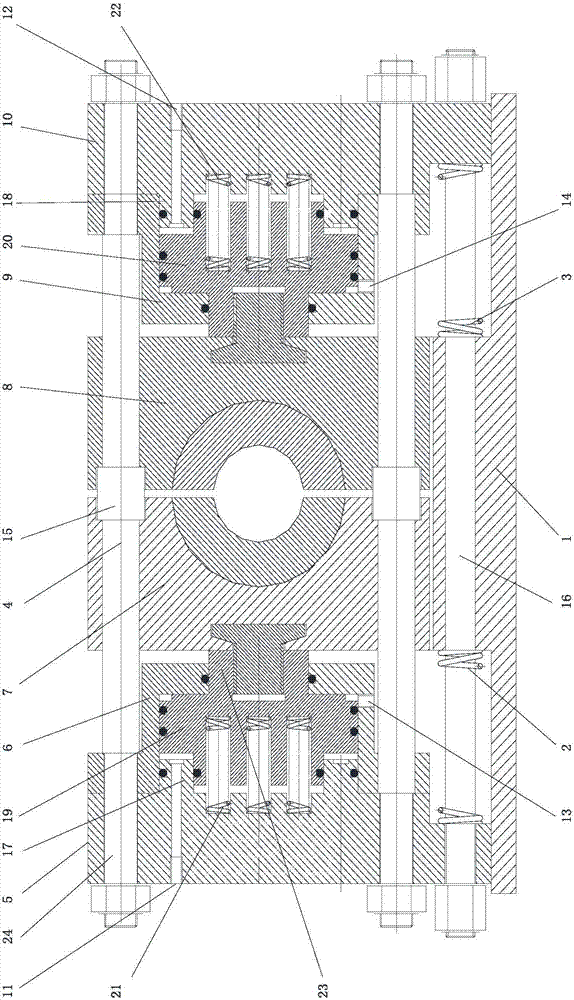
[0023] figure 1 It is a schematic diagram of the structure of the present invention, as shown in the figure, the automatic floating centering hydraulic clamp in this embodiment; includes a clamping assembly for clamping a drill rod and is fixedly matched with the drilling machine frame and used for installing the clamping assembly The base 1; the clamping assembly is installed on the base 1 in a single degree of freedom sliding manner along the radial swing direction of the drill rod; by sliding the clamping assembly on the base 1 in a single degree of freedom along the radial swing direction of the drill rod, The clamping hole of the clamping assembly can be automatically centered with the drill rod, that is, uniform clamping of the drill rod can be realized.

[0024] In this embodiment, a fixed elastic force for fixing the clamping component to prevent the clamping component from sliding under the action of gravity is provided between the base 1 and the clamping component al...


PUM


Abstract

The invention discloses an automatic floating centering hydraulic clamp holder. The automatic floating centering hydraulic clamp holder comprises a clamping assembly used for clamping a drill rod and a base fixedly matched with a drilling machine rack and used for installing the clamping assembly. The clamping assembly is installed on the base in the radial swing direction of the drill rod in a single-degree-of-freedom sliding mode, and a fixing elastic part used for fixing the clamping assembly to avoid the situation that the clamping assembly slides under the gravity effect is arranged between the base and the clamping assembly in the single-degree-of-freedom sliding direction of the clamping assembly; external force floating centering can be increased, so that the situation that abrasion on the drill rod during clamp holder centering is guaranteed through force generated by rotating of the drill rod is avoided; and meanwhile in a lateral orientation drilling machine, the clamp holder can also be centered under the effect of floating external force, so that the eccentric problem of an existing clamp holder under the gravity effect or the problem that the initial position of the clamp holder is repeatedly adjusted to ensure centering in different orientations is avoided.

Description

technical field [0001] The invention relates to the field of drilling tools, in particular to an automatic floating centering hydraulic clamp. Background technique [0002] The gripper is one of the key components in the hydraulic drilling rig. Its structure directly affects the clamping and opening functions of the drill pipe and causes the wear of the drill pipe. The existing grippers are mainly normally closed floating hydraulic grippers, which use disc springs to clamp the drill pipe, and use the floating gap between the gripper seat and the mounting seat to realize the centering of the drill pipe and the gripper. The main defects are In the process of opening and clamping, the floating movement of the drill pipe is realized by using the force on the slips during the rotation of the drill pipe, so as to achieve the purpose of "centering". In fact, it is to ensure that the drill pipe does not continue to contact with the drill pipe after opening. The main performance is ...

Claims


Application Information

Patent Timeline
Patent Type & Authority Applications(China)
IPC IPC(8): E21B19/10E21B19/24
CPCE21B19/10E21B19/24
Inventor 阮绍刚李学忠张凌蒋开勇马振刚陈航田乐意杜渔舟邱响林陈龙王志锦陈艳郑竹林
Owner CHINA COAL TECH & ENG GRP CHONGQING RES INST CO LTD
Learn More