Hydraulic system for packaging machine and working method thereof

A hydraulic system and hydraulic source technology, applied in mechanical equipment, fluid pressure actuators, servo motors, etc., can solve problems such as low packaging efficiency and easy failures, and achieve the goals of convenient operation, safety assurance, and power resource saving Effect

Active Publication Date: 2017-12-01
上海意称液压系统有限公司
View PDF9 Cites 4 Cited by
  • Summary
  • Abstract
  • Description
  • Claims
  • Application Information

AI Technical Summary

Problems solved by technology

[0005] In view of the problem that the hydraulic system of the original baler is prone to failure, resulting in low packing efficiency, the purpose of

Method used


Image

  • Hydraulic system for packaging machine and working method thereof
  • Hydraulic system for packaging machine and working method thereof
  • Hydraulic system for packaging machine and working method thereof

Examples


Embodiment Construction

[0046]In order to make the purpose, technical solutions and beneficial effects of the present invention clearer, the present invention will be further described in detail below in conjunction with the examples and accompanying drawings, but the embodiments of the present invention are not limited thereto.

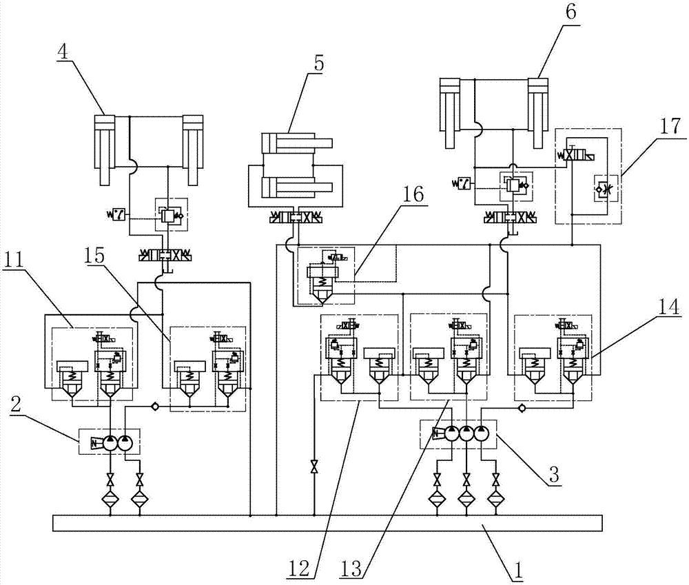
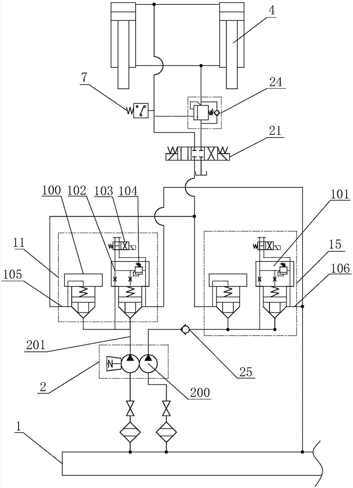
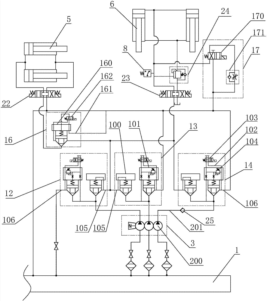
[0047] The solid line in the figure is the working pipeline, the dotted line is the control pipeline, and the dotted line is the module group.

[0048] A hydraulic system of a baler, such as figure 1 As shown, the hydraulic source 1 is included, and the hydraulic source 1 is connected with the first oil pump 2 and the second oil pump 3; the first oil pump 2 includes two hydraulic pumps 200 connected in parallel, and the oil outlet of the first oil pump 2 is connected with two oil outlet pipelines 201 and lead to the first cartridge valve group 11 and the fifth cartridge valve group 15 respectively, the second oil pump 3 includes three hydraulic pumps 200 connected in parall...


PUM


Abstract

The invention discloses a hydraulic system for a packaging machine. The hydraulic system for the packaging machine comprises a hydraulic source; the hydraulic source is connected with a first oil pump and a second oil pump; the first oil pump is connected with a first cartridge valve bank; the first cartridge valve bank communicates with a first three-position four-way valve; the first three-position four-way valve is connected with a pre-loading cylinder; the second oil pump is connected with a second cartridge valve bank, a third cartridge valve bank and a fourth cartridge valve bank simultaneously; the cartridge valve banks are connected with a second three-position four-way valve and a third three-position four-way valve; the second three-position four-way valve is connected with a box body cylinder; and the third three-position four-way valve is connected with a main pressure cylinder. According to the hydraulic system for the packaging machine, the cartridge valve banks cooperate with the three-position four-way valves to achieve the effects of protecting and controlling an oil way; the pre-loading cylinder moves independently and can be selectively controlled; the box body cylinder and the main pressure cylinder mainly achieve an effect of assisting packaging; power resources are saved; power usage efficiency is improved; the oil way is controlled through a plurality of control ends; normal connecting and disconnecting of the oil way in a working process of the packaging machine are ensured; the packaging machine is safer; meanwhile, a plurality of moving stations of the packaging machine are controlled through three cylinder blocks; and the operation is more convenient.

Description

technical field [0001] The invention relates to the field of control systems of balers, more specifically, it relates to a hydraulic system of balers and a working method thereof. Background technique [0002] The baler is also called a baler, a strapping machine or a strapping machine. By using strapping straps to bundle products or tightening irons, the products are stored and arranged to avoid products from being scattered during transportation. In order to ensure smooth operation, hydraulic pressure is usually used. The system takes control. [0003] In response to the above problems, the Chinese patent with the patent announcement number CN106499684A proposes a hydraulic system for a baler, including a plunger pump and an electric motor. The plunger pump is connected with a stop valve, a throttle valve, a filter, an overflow valve, and a throttle The valve is connected with the three-position four-way valve, and the three-position four-way valve is connected with the m...

Claims


Application Information

Patent Timeline
IPC IPC(8): F15B11/17F15B13/02
CPCF15B11/17F15B13/02
Inventor 刘占锋胡德庆郭栋
Owner 上海意称液压系统有限公司
Why Eureka
Try Eureka