Working method for gesture-sensing mirror front illuminating lamp

A technology of gesture sensing and working methods, which is applied to the components of lighting devices, lighting devices, fixed lighting devices, etc., can solve problems such as internal circuit corrosion, insufficient lighting, and dirty switch surfaces, and achieve reasonable structural design and convenient use , Keep the surface clean and tidy

Inactive Publication Date: 2017-12-01
太仓市普利照明电器有限公司
3 Cites 0 Cited by

AI-Extracted Technical Summary

Problems solved by technology

[0003] In order to make full use of the space in the existing building design, most bathrooms are prone to insufficient lighting. When entering the bathroom, it is usually necessary to turn on the lighting, and the mirror front light is a new type of home lighting product, which has been widely used at present. However, there are obvious deficiencies in the mirror headlights of the existing structure, because people habitually turn on the lights when they enter the bathroom for washin...

Abstract

The invention discloses a working method for a gesture-sensing mirror front illuminating lamp. The gesture-sensing mirror front illuminating lamp comprises a lamp body, wherein a gesture sensing switch is arranged on the lamp body; a lampshade, a radiating pedestal and a light assembly are arranged in the lamp body; the light assembly is arranged in the lampshade; the radiating pedestal is arranged below the light assembly; the gesture sensing switch comprises a gesture sensor, a data converting and processing unit, a controller and a light control unit; an output end of the gesture sensor is electrically connected with an input end of the data converting and processing unit; an output end of the data converting and processing unit is connected with an input end of the controller; an output end of the controller is electrically connected with an input end of the light control unit; and an output end of the light control unit is electrically connected with the light assembly. The mirror front lamp can be switched on and switched off anytime through gesture sensing according to the needs in a washing process, so that hands covered with water or lotion are prevented from directly touching a power supply switch to start the switch, and therefore, the surface of the power supply switch is kept clean.

Application Domain

Lighting support devicesElectrical apparatus +5

Technology Topic

ElectricityEngineering +1

Image

  • Working method for gesture-sensing mirror front illuminating lamp
  • Working method for gesture-sensing mirror front illuminating lamp

Examples

  • Experimental program(1)

Example Embodiment

[0024] Example
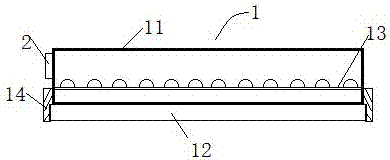
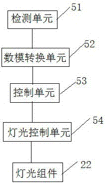
[0025] Such as Figure 1-2 The working method of a gesture-sensing mirror front illuminator is characterized in that it includes a lamp body 1, which is provided with a hand sweep sensor switch 2, and the lamp body 1 includes a lamp shade 11, a heat dissipation base 12 and The lighting assembly 13, the lighting assembly 13 is located in the lampshade 11, the heat dissipation base 12 is arranged under the lighting assembly 13, and the hand scanning sensor switch 2 includes a gesture sensor 21, a data conversion processing unit 22, and a controller 23 and a light control unit 24. The output end of the gesture sensor 21 is electrically connected to the input end of the data conversion processing unit 22, the output end of the data conversion processing unit 22 is connected to the input end of the controller 23, and the control The output end of the device 23 is electrically connected to the input end of the light control unit 24, and the output end of the light control unit 24 is electrically connected to the light assembly 13;
[0026] The specific working methods are as follows:
[0027] (1) Put your hand into the hand-scan sensor switch 2 of the lamp body 1, and when the gesture sensor (21) detects that the object enters the sensing area, it transmits the detection signal to the data conversion processing unit 22;
[0028] (2) The data conversion processing unit 22 converts the detected analog signal into a digital signal;
[0029] (3) After the signal conversion is completed, the digital signal is transmitted to the controller 23, and the controller 23 controls the lighting control unit 24 to turn on the lighting assembly 13;
[0030] (4) When the gesture sensor 21 detects the sensing area that the object enters for the second time, it detects and sends a shutdown signal to the controller 23, and the controller 23 controls the lighting assembly 13 to turn off.
[0031] In this embodiment, the light assembly 13 includes an LED light board, the LED light board is provided with LED lamp beads, the LED lamp bead is provided with a protective layer, and the protective layer is made of a thermally conductive insulating colloidal material.
[0032] In this embodiment, the lamp cover 11 and the heat dissipation base 12 are detachably connected, and a sealing device is provided between the lamp cover 11 and the heat dissipation base 12.
[0033] In this embodiment, the controller 23 includes an induction detection module, a processor module, and a light brightness control module, and both the induction detection module and the light brightness control module are electrically connected to the processor module.
[0034] This embodiment also includes an installation fixing device, the installation fixing device includes a hanging piece and a fixed installation piece, the hanging piece is arranged above the lamp body, the fixed installation piece is fixedly installed with the wall, and the fixed installation piece is provided There are through holes that match the hanging piece.
[0035] In this embodiment, the inner wall of the lampshade 11 is coated with a phosphor layer for light guide.
[0036] In this embodiment, the gesture sensor 21 is a non-contact displacement sensor.
[0037] In this embodiment, the light control unit 24 drives the brightness of the light assembly to change.

PUM

no PUM

Description & Claims & Application Information

We can also present the details of the Description, Claims and Application information to help users get a comprehensive understanding of the technical details of the patent, such as background art, summary of invention, brief description of drawings, description of embodiments, and other original content. On the other hand, users can also determine the specific scope of protection of the technology through the list of claims; as well as understand the changes in the life cycle of the technology with the presentation of the patent timeline. Login to view more.

Similar technology patents

Aggregate screening device for buildings

Owner:SHENZHEN SHENGTENG ENTERPRISE MANAGEMENT CO LTD

Draw-bar box with external article placing groove

PendingCN107212547AReasonable structural design
Owner:ZHEJIANG HONGYI CASES & LEATHER

Energy saver for base station machine room air conditioners

ActiveCN101943453AReasonable structural designSolve the problem of high power consumption
Owner:亿宏技术有限公司

Classification and recommendation of technical efficacy words

  • Reasonable structural design
  • easy to use

Bolt machining all-in-one machine

Owner:ANHUI LIUFANG ZHONGLIAN MECHANICAL SHARE

Automatic operation device of upper drill floor and lower drill floor of drill rod

InactiveCN102230364AReasonable structural designEasy and reliable operation
Owner:SHENGLI OIL FIELD HAISHENG ENVIRONMENTAL PROTECTION ENG

High-precision vertical type machining center

ActiveCN104802038AReasonable structural designImprove rigidity and stability
Owner:普锐米勒机床(东莞)有限公司
Why Eureka
Try Eureka