Device and method for weakening rarefaction wave of hydrogen-oxygen detonation shock tube

A sparse wave and shock tube technology, which is applied in the field of devices for weakening the sparse wave of hydrogen-oxygen detonation shock tube, can solve the problems of increasing the length of the detonation driving section, increasing the size of the equipment, affecting the test results, etc. Effect of flow time, increased presence time, increased experimental time

Active Publication Date: 2017-12-01
WUHAN UNIV OF TECH
View PDF5 Cites 7 Cited by
  • Summary
  • Abstract
  • Description
  • Claims
  • Application Information

AI Technical Summary

Problems solved by technology

However, increasing the length of the detonation driving section will increase the size of the equipment accordingly, resulting in increased gas consumption and increased experimental costs; expanding the cross-sectional area of ​​the detonation driving section means using a driven section with a smaller diameter than the driving section , considering the needs of the shock wave injury experiment, the driven section is often connected to the large-diameter experimental section, and the shock wave intensity will be greatly attenuated at the expansion section from the small-diameter driven section to the large-diameter experimental section, which is not conducive to the test and affects Test results; the method of inserting an annular cavity and double detonation drive at the diaphragm will make the device structure complicated and costly

Method used


Image

  • Device and method for weakening rarefaction wave of hydrogen-oxygen detonation shock tube
  • Device and method for weakening rarefaction wave of hydrogen-oxygen detonation shock tube

Examples


Embodiment Construction

[0022] In order to make the objectives, technical solutions, and advantages of the present invention clearer, the following further describes the present invention in detail with reference to the accompanying drawings and embodiments. It should be understood that the specific embodiments described here are only used to explain the present invention, but not to limit the present invention.

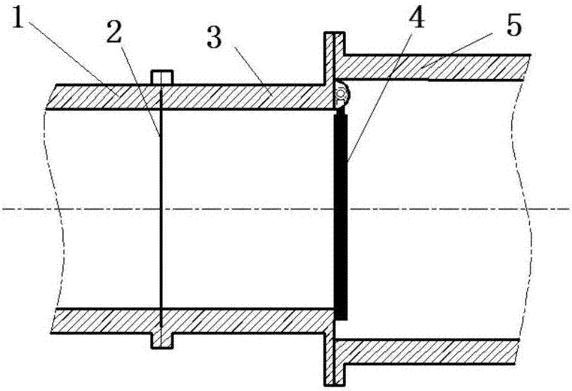
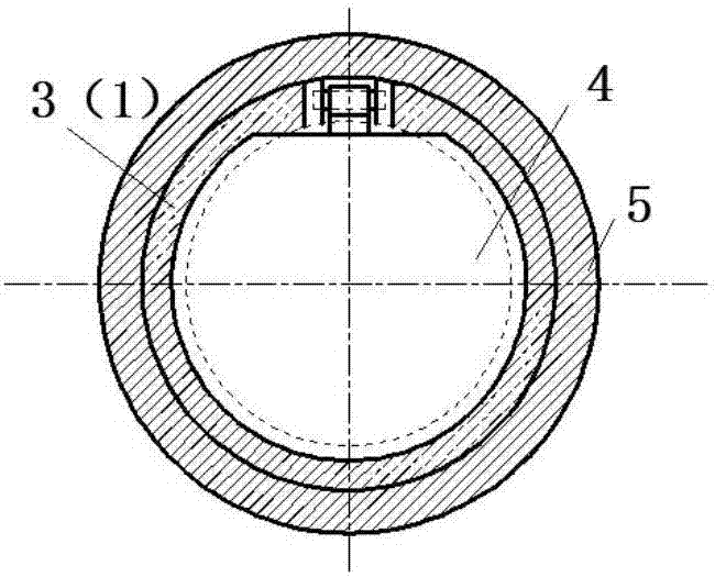
[0023] See figure 1 with figure 2 , A device for attenuating the sparse wave of a hydrogen-oxygen detonation shock tube, which includes a detonation drive section 1, a transition section 3, a driven section 5, a diaphragm 2 and a baffle 4, a detonation drive section 1, a transition section 3 The inner and outer pipe diameters are the same, the inner diameter of the driven section 5 is 60-100mm larger than the inner diameter of the detonation drive section 1 and the transition section 3 (that is, the installation space of the hinge structure is 30-50mm); the detonation drive section 1, The tr...


PUM


Abstract

The invention discloses a device for weakening the rarefaction wave of a hydrogen-oxygen detonation shock tube, which includes a detonation driving section, a transition section, a driven section, a diaphragm and a baffle. The detonation driving section, the transition section and the driven section are connected in sequence. The diaphragm is arranged at the joint of the detonation driving section and the transition section. The baffle is arranged at the joint of the transition section and the driven section. The upper end of the baffle is hinged to the pipe of the transition section or of the driven section. After the incident shock wave formed by the detonation driving section breaks the diaphragm, the baffle is lifted up to allow the incident shock wave to pass and be propagated to the driven section. Part of the incident shock wave is reflected by the baffle and interferes with rarefaction wave, so that the attenuation effect of the rarefaction wave on the incident shock wave is weakened, and the steady flow time of the incident shock wave is prolonged. After the incident shock wave passes through the baffle, the baffle is closed again under the action of gravity. The invention further provides a method for weakening the rarefaction wave of a hydrogen-oxygen detonation shock tube. Through the device and the method, the rarefaction wave of a hydrogen-oxygen detonation shock tube can be weakened, and the steady gas flow used in experimental study can exist longer.

Description

Technical field [0001] The invention relates to a device and method for weakening the sparse wave of a hydrogen-oxygen detonation shock tube, which is mainly used for simulating the propagation law of shock wave in an explosive environment and the shock injury experiment research. Background technique [0002] The hydrogen-oxygen detonation shock tube is powered by chemical energy released by instantaneous detonation, and its driving capability is much higher than that of a shock tube driven by high-pressure hydrogen / helium gas. In order to generate incident shock waves of the same intensity, the latter requires a driving pressure several times that of the former. Therefore, the equipment driven by the hydrogen-oxygen detonation is simpler, consumes less gas, and has lower experimental costs. See Jiang Zonglin and Li Jinping for details. , Zhao Wei, Liu Yunfeng, Yu Hongru's long test time detonation drive shock wave wind tunnel technology research, 2012, 05: 824-831. [0003] For ...

Claims


Application Information

Patent Timeline
Patent Type & Authority Applications(China)
IPC IPC(8): G01M9/06
CPCG01M9/065
Inventor 何松李乾马力孙国翔陈先锋
Owner WUHAN UNIV OF TECH
Why Eureka
Try Eureka