plant cultivation system

A plant and cultivation tank technology, applied in the field of plant cultivation system, can solve problems such as complex structure, shortened life span, length deformation, etc., and achieve the effect of simple installation and maintenance management, no shortened life span, and reduced cost burden

Active Publication Date: 2020-12-22
GREEN PLUS CO LTD +1
View PDF9 Cites 0 Cited by
  • Summary
  • Abstract
  • Description
  • Claims
  • Application Information

AI Technical Summary

Problems solved by technology

[0004] However, the above-mentioned a large number of plant cultivation systems with registered patents use a plurality of roller hooks, left and right moving pipes, sprockets or pulleys, and lifts when lifting and lowering the left and right cultivation tanks in turn, and forming a movement channel for operators based on the rising cultivation tanks. chain or iron wire, so there are problems such as complex structure, installation and maintenance management are very inconvenient, in addition, at the lower end of multiple hooks, the sprocket or pulley of the lifting chain or iron wire and the two adjacent hooks of the hooks are installed through the shaft As a group, the corresponding part in the middle of the two hooks of each group is bound and fixed with the left or right moving tube, and the fixed part is taken as the reference, so that the left part of the cultivation tank installed at the lower end passes through the sprocket of the left position hook Or the pulley is connected downwards. When the right part of the cultivation tank is installed at the lower end and is connected downwards through the sprocket or pulley of the hook at the right position, a long lifting chain or iron wire must be used. At this time, the load of the cultivation tank may cause the length to be deformed, thereby There is a problem of shortened lifespan

Method used


Image

  • plant cultivation system
  • plant cultivation system
  • plant cultivation system

Examples


Embodiment Construction

[0039] The plant cultivation system of the embodiment of the present invention will be described in detail below with reference to the accompanying drawings.

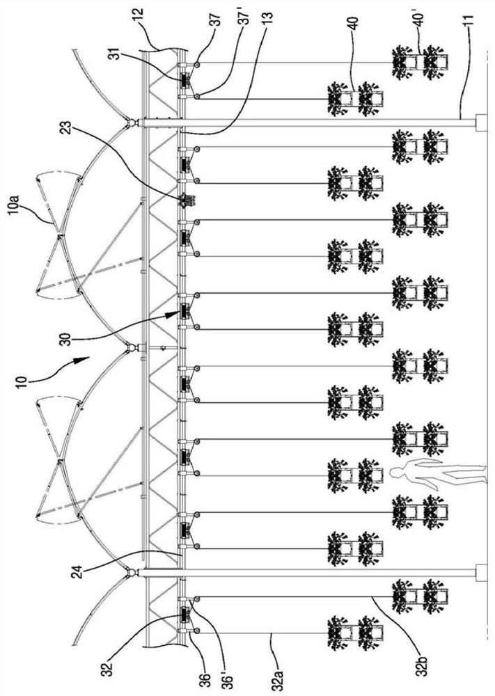
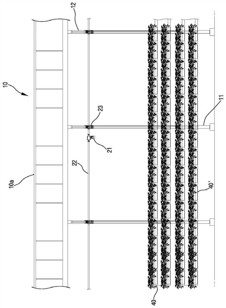
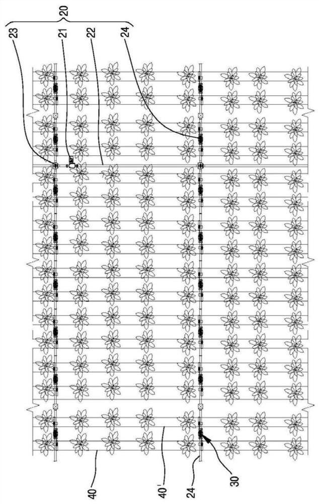
[0040] figure 1 It is a partial front view of the greenhouse in which the plant cultivation system according to the first embodiment of the present invention is installed; figure 2 yes figure 1 A schematic side view of the plant cultivation system of ; image 3 yes figure 1 A rough plan of the plant cultivation system; Figure 4 yes figure 1 A partially enlarged front view of a part of ; Figure 5a-5c yes Figure 4 Partially enlarged front, plan and side views of a lifting means in .

[0041] Figure 1 to Figure 5a - Figure 5c The plant cultivation system of the first embodiment of the present invention is characterized in that it includes: the drive means 20 installed on the truss 12 above the inner column 11 of the greenhouse 10 that horizontally traverses the commonly used roof structure 10a as usual; A p...


PUM


Abstract

The present invention relates to a plant growing system making an overall greenhouse area be used as a space capable of growing a plant, so mass-production is possible. The plant growing system according to an embodiment of the present invention comprises: a plurality of driving means (20) installed at predetermined forward and backward intervals to laterally cross a truss horizontally crossing the top of a greenhouse, and including motors (21) and driving shafts (22); an ascending means (30) including drums (31) axially fixed to the driving shafts at predetermined lateral intervals and having winding grooves (311) spirally formed thereon, wires (32), first left and right guiding pulleys (34, 34), and second left and right guiding pulleys (37, 37), wherein the wires (32) have middle parts wound on the middle of each of the winding grooves of the drums, left parts (32a) facing a bottom side in the left front sides of the drums, and right parts (32b) facing a bottom side in the right rear sides of the drums, and the first left and right guiding pulleys (34, 34) and second left and right guiding pulleys (37, 37) are hung on the top and bottom sides of the wires to widen intervals in the left and right sides of the wires; and growing gutters (40, 40) coupled with the left and right bottoms of the wires, and made to ascend by means of the ascending means.

Description

technical field [0001] The present invention relates to a plant cultivation system, specifically, a plant cultivation system that uses the entire greenhouse area as a space for cultivating plants, enabling mass production. Background technique [0002] In the past, when soil cultivation or soilless cultivation was carried out in the greenhouse, the operator passage for sowing, cultivation management or harvesting accounted for at least half of the greenhouse area, so the cultivation area was halved, and the yield was greatly reduced, resulting in production loss. Costs and consumer prices have risen, and the burden on producers and consumers has increased. [0003] In order to solve the above-mentioned problems, the applicant of the present invention provides a plant cultivation device (Korean registered patent No. 10-1251903), comprising: a motor fixedly installed on a truss that crosses the greenhouse above the greenhouse, installed on the motor The driving means is compo...

Claims


Application Information

Patent Timeline
Patent Type & Authority Patents(China)
IPC IPC(8): A01G9/02A01G9/14
CPCA01G9/024A01G9/14Y02A40/25A01G9/1423A01G9/143
Inventor 朴荣焕
Owner GREEN PLUS CO LTD
Why Eureka
Try Eureka