Communication machine room with partitioned cooling function

A technology for communication equipment rooms and equipment rooms, which is applied in space heating and ventilation, space heating and ventilation details, and household heating, etc. It can solve the problem of reducing heat dissipation efficiency, breakdown damage of components, affecting circuit stability and reliability, etc. problems, to achieve the effect of reducing the damage rate, reducing the damage rate, and improving the heat dissipation efficiency

Inactive Publication Date: 2017-12-05
XIANGJIANG TECH
View PDF4 Cites 7 Cited by
  • Summary
  • Abstract
  • Description
  • Claims
  • Application Information

AI Technical Summary

Problems solved by technology

If the temperature is too high, it is easy to cause poor heat dissipation of the machine, causing the working parameters of the transistor to drift, affecting the stability and reliability of the circuit, and even causing breakdown damage to components in serious cases.
Traditional communication equipment rooms use an air inlet and an exhaust outlet to achieve air circulation to reduce the temperature inside the equipment room, but because the efficiency of each type of telecommunications equipment is different, the heat generated is different, and because the telecommunications equipment in the equipment room is arranged closely , the heat dissipation system with one air inlet and one air outlet will cause low air circulation efficiency in the machine room, and cannot achieve targeted heat dissipation effect, thereby reducing heat dissipation efficiency and significantly increasing the damage rate of telecommunication equipment

Method used


Image

  • Communication machine room with partitioned cooling function
  • Communication machine room with partitioned cooling function
  • Communication machine room with partitioned cooling function

Examples


Embodiment Construction

[0017] In order to make the content of the present invention more clearly understood, the present invention will be further described in detail below based on specific embodiments and in conjunction with the accompanying drawings.

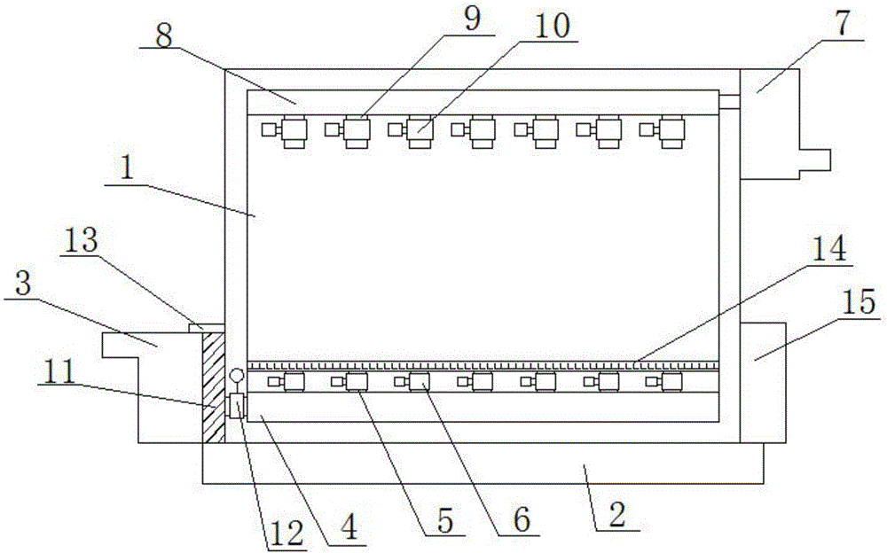
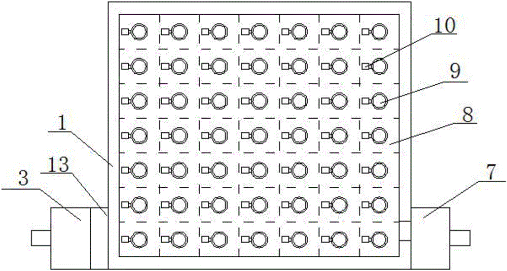
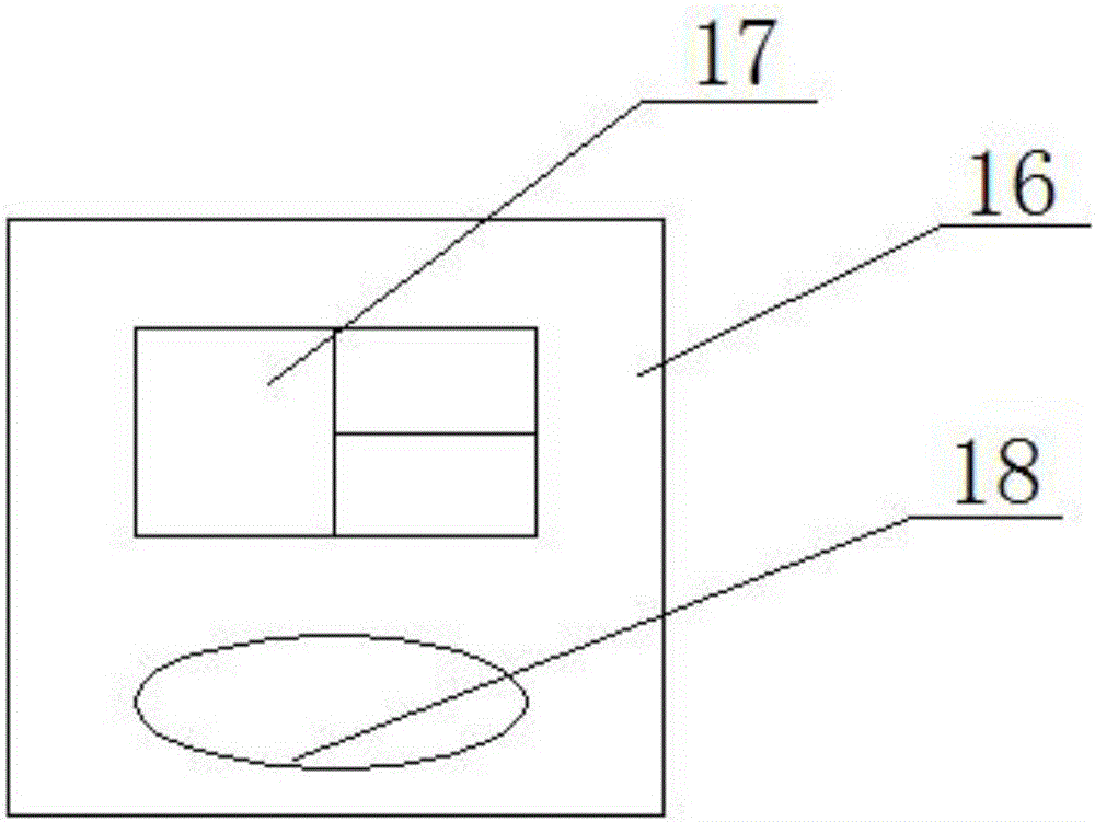
[0018] like Figure 1-4 As shown, a communication machine room with partition heat dissipation function includes a machine room body 1, a base 2 arranged on the lower side of the machine room body 1, an exhaust device arranged at the upper end of the machine room body 1, and an air exhaust device arranged at the lower end of the machine room body 1. The air inlet device and the control device arranged on one side of the machine room body 1, the air inlet device includes an air inlet fan 3 and an air inlet chamber 4, the outlet of the air inlet fan 3 is connected with the air inlet chamber 4, and the air inlet chamber The upper side of 4 is uniformly provided with a plurality of air inlets 5, and the air inlet 5 is provided with an air inlet electro...


PUM


Abstract

The invention discloses a communication machine room with a partitioned cooling function. The communication machine room comprises a machine room body, a base, an air exhaust device, an air intake device and a control device. The air intake device comprises an air intake fan and an air intake cavity. An outlet of the air intake fan is connected with the air intake cavity through a filter screen. The upper side of the air intake cavity is uniformly provided with a plurality of air inlets. Air intake solenoid valves are arranged on the air inlets. The air exhaust device comprises an exhaust fan and an exhaust cavity. The exhaust cavity communicates with an inlet of the exhaust fan. The lower side of the exhaust cavity is uniformly provided with a plurality of exhaust ports. Exhaust solenoid valves are arranged on the exhaust ports. A temperature sensor is arranged in the position, located between each pair of the exhaust port and the air inlet which correspond to each other up and down, of the interior of the room. The area of the whole machine room can be uniformly partitioned. Targeted cooling treatment is conducted on the areas with different temperatures in the machine room. The cooling efficiency is improved. The damage rate of communication equipment is reduced.

Description

technical field [0001] The invention relates to a communication machine room with partition heat dissipation function, which is suitable for the field of communication machine rooms. Background technique [0002] As people's demand for information exchange increases day by day, the information industry has maintained rapid development for several consecutive years. The transmission of information in all walks of life is inseparable from communication services. In communication services, the communication room is an important place to support the normal operation of the information system. In order to ensure the safety of equipment and information in the computer room, and to ensure a good operating environment and working order in the computer room, it is very important to maintain and manage the communication computer room reasonably and effectively. Telecommunications equipment, especially switches, have high requirements on the temperature of the equipment room. If the...

Claims


Application Information

Patent Timeline
Patent Type & Authority Applications(China)
IPC IPC(8): F24F5/00F24F13/06F24F13/28
CPCF24F5/00F24F13/06F24F13/28
Inventor 崔兵张福生黄永生
Owner XIANGJIANG TECH
Why Eureka
Try Eureka