Multifunctional power meter reading tool
A multi-functional, electric power technology, applied in the direction of TV, electrical components, closed-circuit television systems, etc., can solve the problems of wasting time, low efficiency of personnel work, high labor intensity, etc., achieve convenient use, save meter reading time, and reduce labor intensity Effect
- Summary
- Abstract
- Description
- Claims
- Application Information
AI Technical Summary
Problems solved by technology
Method used
Image
Examples
Embodiment 1
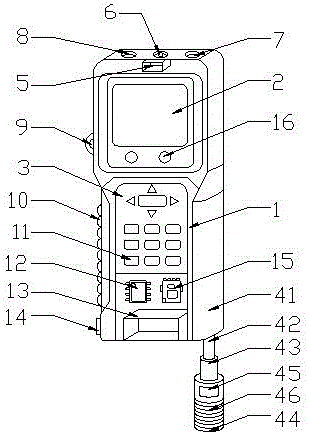
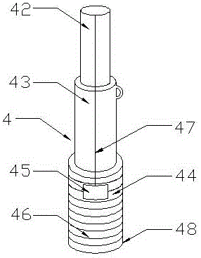
[0019] Such as figure 1 As shown, a multifunctional power meter reading tool includes a meter reading instrument main body 1 and a display screen 2, and the display screen 2 is arranged at the upper center of the meter reading instrument main body 1, and also includes an operation panel 3 and a meter reading telescopic support 4 , camera 5, lighting lamp 6, non-contact humidity sensor 7, non-contact temperature sensor 8, switch key 9, insulating shell 10, input button 11, data processor 12, battery compartment 13, USB interface 14, data collector 15 and Indicator light 16, the operation panel 3 is arranged on the meter reading instrument main body 1 at the bottom of the display screen 2, the meter reading instrument main body 1 on the side of the operation panel 3 is equipped with a meter reading telescopic support 4, the operation panel 3 An input button 11 is arranged on the screen, a camera 5 is installed on the main body 1 of the meter reading instrument on the upper side ...
Embodiment 2
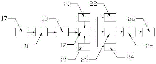
[0022] The difference between this embodiment and embodiment 1 is: as image 3 As shown, the input of the data processor 12 is connected to the output of the interference filter module 19, the prompter module 20 and the button module 21, and the input of the interference filter module 19 is connected to the output of the meter reading camera module 18 The input end of the meter reading camera module 18 is connected with the electric meter module 17, and the output end of the data processor 12 is connected with a display module 22, an electricity bill statistics module 23 and a storage module 24.
[0023] Wherein, the output end of the electricity bill statistics module 23 is connected to the input end of the wireless network sending module 25 , and the output end of the wireless network sending module 25 is connected to the input end of the user mobile phone module 26 .
Embodiment 3
[0025] The difference between this embodiment and embodiment 1 is: as Figure 4 As shown, a fixed structure 27 is installed on the side opposite to the display screen 2 of the meter reading instrument main body 1, and the fixed structure 27 includes a finger fixing ring 271 and a ring groove 272, and the finger fixing ring 271 is connected to the meter reading instrument The main bodies 1 are connected in rotation, and the finger fixing ring 271 is arranged in the ring groove 272 through rotation.
[0026] The use state of the present invention is: the present invention has reasonable and simple structure, low production cost, easy to use, here at first by being installed on the meter reading telescopic bracket 4 on the meter reading instrument main body 1 side, the telescopic cover rod of the meter reading telescopic bracket 4 41 is integrated with the main body 1 of the meter reading instrument. By stretching the first telescopic rod 42 and the second telescopic rod 43 in th...
PUM
 Abstract
Description
Claims
Application Information
 - R&D
- Intellectual Property
- Life Sciences
- Materials
- Tech Scout
- Unparalleled Data Quality
- Higher Quality Content
- 60% Fewer Hallucinations
Browse by: Latest US Patents, China's latest patents, Technical Efficacy Thesaurus, Application Domain, Technology Topic, Popular Technical Reports.
© 2025 PatSnap. All rights reserved.Legal|Privacy policy|Modern Slavery Act Transparency Statement|Sitemap|About US| Contact US: help@patsnap.com


