Damage-proof plastic crushing machine capable of separating metal impurities

A technology for separating metal and metal impurities, applied in the field of plastic manufacturing, can solve the problems of damage to the pulverizer blade, high noise, insufficient pulverization, etc., and achieve the effect of prolonging the service life, reducing wear and reducing dust.

Inactive Publication Date: 2017-12-08
SUZHOU HENGDAL IND MATERIALS CO LTD
7 Cites 8 Cited by

AI-Extracted Technical Summary

Problems solved by technology

[0002] Plastic pulverizers are widely used in the plastic manufacturing industry. The raw materials of existing plastic pulverizers are generally from recycled plastic waste, and there are many impurities. Non-metallic impurities can generally be removed clearly by liquid, and metal impurities are often mixed into plastic raw materials, which often block injection molding. The nozzle of the grinder will damage the blade of the grinder and scratch the cylinder o...

Abstract

The invention discloses a damage-proof crushing machine capable of separating metal impurities. The damage-proof crushing machine capable of separating metal impurities is characterized by comprising a hobbing cutter set (10), a roller cutter set (20), a first feeding cylinder (30), a second feeding cylinder (80), powder isolation plates (40), a screen (50), a discharging cylinder (60), a box (70), a metal separator (100) and a motor. According to the damage-proof crushing machine capable of separating metal impurities, metal particles can be separated from plastic particles, and the service life of blades of the plastic crushing machine is prolonged; meanwhile, the hobbing cutter set and the roller cutter set are used in combination for plastic crushing, so that abrasion of the hobbing cutter set is reduced, and the service life of the cutter sets is prolonged; and the roller cutter set is sealed through the two feeding cylinders, so that dust is reduced, and noise is lowered.

Application Domain

Plastic recyclingMagnetic separation +2

Technology Topic

PulverizerKnife blades +4

Image

  • Damage-proof plastic crushing machine capable of separating metal impurities
  • Damage-proof plastic crushing machine capable of separating metal impurities

Examples

  • Experimental program(1)

Example Embodiment

[0028] The present invention will be further described below in conjunction with the drawings.
[0029] In order to make it easy to understand the creative characteristics, the purpose and the effects of the technical means realized by the present invention, the present invention will be further explained below in conjunction with specific embodiments.
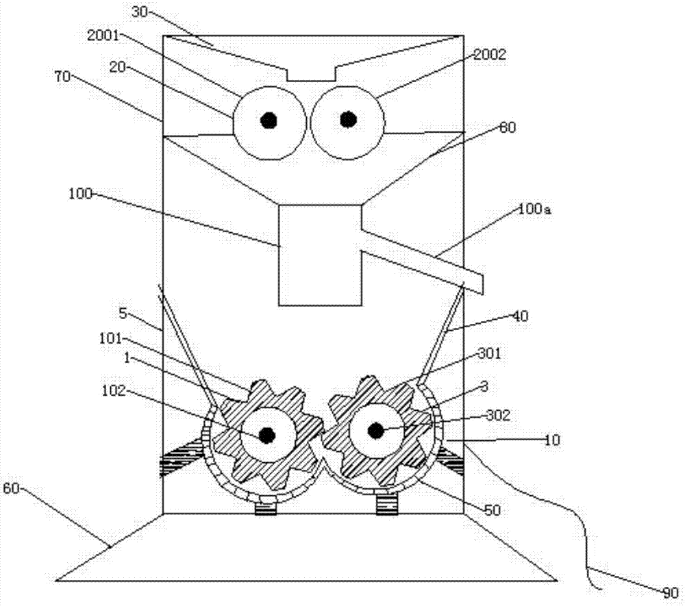
[0030] See figure 1 , A loss-proof plastic pulverizer capable of separating metal impurities, including a hob cutter set 10, a drum cutter set 20, a first feeding barrel 30, a second feeding barrel 80, a powder partition 40, and a screen 50 , The discharge barrel 60, the box body 70, the metal separator 100 and the motor;
[0031] The hob cutter set 10, the drum cutter set 20, the first feed cylinder 30, the second feed cylinder 80, the powder partition 40 and the screen 50 are all arranged in the box 70, and the discharge cylinder 60 is fixedly arranged in the box. Below the body; the motor is arranged outside the box body 70;
[0032] The drum knife set 20 is arranged between the first feeding barrel 30 and the second feeding barrel 80, the metal separator 100 is arranged below the second feeding barrel 80, and the metal impurity discharge barrel 100a of the metal separator 100 extends out of the box. Body 70, the hob cutter set 10 is arranged below the plastic outlet of the metal separator 100; after the powder partition 40 is fixedly connected to the screen 50, the box body 70 is partitioned, and the screen 50 is arranged below the hob cutter set 10. The powder separator 40 has a funnel shape and can collect all the plastic raw materials processed by the metal separator.
[0033] Such as figure 2 As shown, the metal separator 100 further includes a separator blanking barrel 100b, a separator feeding barrel 100c, a metal detection circuit 100d, and a metal separation switch valve 100e;
[0034] The metal detection circuit 100d is connected to the metal separation switch valve 100e, and controls the metal separation switch valve 100e to switch;
[0035] The separator blanking barrel 100b is fixedly arranged under the separator feeding barrel 100c, and the metal detection circuit 100d is arranged on the upper end of the side of the separator blanking barrel 100b; the metal impurity discharge barrel 100a is fixedly arranged at the lower end of the separator blanking barrel 100b , And the metal impurity discharge cylinder 100a is set diagonally downward;
[0036] The metal separation switch valve 100e is arranged at the feed end of the metal impurity discharge cylinder 100a.
[0037] A detachable magnet is provided on the outer surface of the metal impurity discharge cylinder 100a.
[0038] The metal impurity discharge cylinder 100a is made of plastic.
[0039] The drum cutter set 20 includes a fixed wheel group 2001 and a runner wheel group 2002. The fixed wheel group includes a fixed wheel shaft and a fixed wheel. The runner wheel group includes a runner shaft and a runner; the fixed wheel shaft and the fixed wheel are fixedly connected, The fixed wheel shaft is connected to the motor to drive the fixed wheel to rotate; the runner shaft is connected to the runner through a bearing; the fixed wheel set 2001 and the runner set 2002 are arranged horizontally, and the fixed wheel set 2001 and the runner set 2002 are set up There are gaps for smashing plastic particles from the gaps. The size of the gaps is set according to the size of the plastic particles.
[0040] The hob cutter set 10 includes a first rotary knife 1 and a fixed rotary knife 3;
[0041] The first rotary knife 1 and the fixed rotary knife 3 are both gear-shaped, and the outer surfaces of the gear-shaped rotary knifes of the first rotary knife 1 and the fixed rotary knife 3 mesh with each other;
[0042] The fixed rotary knife 3 includes a rotary shaft 302 and a third gear-shaped rotary knife 301. The rotary shaft 302 passes through the shaft center of the third gear-shaped rotary knife 301 and is fixedly connected to the third gear-shaped rotary knife 301; the rotary shaft 302 is connected to a motor;
[0043] The first rotary knife 1 includes a first fixed shaft 102, a first gear-shaped rotary knife 101 and a first bearing. The first fixed shaft 102 passes through the shaft center of the first gear-shaped rotary knife 101. The first fixed shaft 102 is connected to the first bearing. The bearings are fixedly connected, and the first gear-shaped rotary knife 101 rotates around a first fixed axis through the first bearing;
[0044] The box body includes a panel 5, and the first fixed shaft 102 and the rotating shaft 302 both pass through and extend out of the panel 5.
[0045] The rotating shaft 302 and the panel 5 are connected by bearings.
[0046] The first fixed shaft 102 is fixedly connected to the panel 5.
[0047] The rotating shaft 302 is used for connecting a motor, and the fixed rotating knife 3 is a driving wheel cutter set.
[0048] The first feeding barrel 30, the second feeding barrel 80 and the box body 70 are all made of metal and connected to the ground 90.
[0049] The above are only the preferred embodiments of the present invention. It should be pointed out that for those of ordinary skill in the art, without departing from the principle of the present invention, several improvements and modifications can be made, and these improvements and modifications are also It should be regarded as the protection scope of the present invention.

PUM

no PUM

Description & Claims & Application Information

We can also present the details of the Description, Claims and Application information to help users get a comprehensive understanding of the technical details of the patent, such as background art, summary of invention, brief description of drawings, description of embodiments, and other original content. On the other hand, users can also determine the specific scope of protection of the technology through the list of claims; as well as understand the changes in the life cycle of the technology with the presentation of the patent timeline. Login to view more.

Similar technology patents

Glomerocryst cubic boron nitride composite sheet and preparation method for same

ActiveCN103158287AExtended service lifeIncreased depth of cut
Owner:ZHENGZHOU BERLT HARD MATERIALS

Sleep assistance mattress

ActiveCN106842979AReduce data processing pressureExtended service life
Owner:DONGGUAN UNIV OF TECH

Application of epoxy cardanol as bio-based hindered phenolic antioxidant

InactiveCN105219458AGood antioxidant propertiesExtended service life
Owner:INST OF CHEM IND OF FOREST PROD CHINESE ACAD OF FORESTRY

Classification and recommendation of technical efficacy words

  • Extended service life
  • reduce wear

Fracturing manifold quick connecting device

Owner:YANTAI JEREH PETROLEUM EQUIP & TECH

Modified asphalt composition with creeping characteristic and preparation method thereof

InactiveCN102020859Aavoid rapid agingExtended service life
Owner:ZHEJIANG WOPUMAN HIGH NEW MATERIALS
Why Eureka
Try Eureka