Integrated type drive-by-wire hydraulic braking device

A hydraulic brake, integrated technology, applied in the direction of brake transmission, brake, transportation and packaging, etc., can solve the problems of large vacuum booster, large engine dependence, complex vehicle layout, etc., to improve driving safety performance, good braking stability, and volume-saving effects

Inactive Publication Date: 2017-12-08
JILIN UNIV
View PDF6 Cites 13 Cited by
  • Summary
  • Abstract
  • Description
  • Claims
  • Application Information

AI Technical Summary

Problems solved by technology

[0002] The braking system of a traditional car usually adopts a vacuum booster structure. Its principle is to use the vacuum negative pressure to increase the force applied by the driver on the pedal to achieve the boosting effect on the driver during the braking process. However, the vacuum booster structure also It has the following significant disadvantages: such as the large volume of the vacuum booster, low integration, complicated layout on the vehicle, high dependence on the engine, and poor reliability. Therefore, vacuum boosters are no longer used on most models at present. device structure
With the rapid development of today's automobile and automobile technology, people's demand for the braking performance of automobiles is gradually increasing, and the demand for high integration of automobile braking devices is also gradually increasing. Obviously, the traditional braking structure cannot meet today's requirements.

Method used


Image

  • Integrated type drive-by-wire hydraulic braking device
  • Integrated type drive-by-wire hydraulic braking device
  • Integrated type drive-by-wire hydraulic braking device

Examples


specific Embodiment approach

[0038] In order to further illustrate the technical solution of the present invention, in conjunction with the accompanying drawings, the specific implementation of the present invention is as follows:

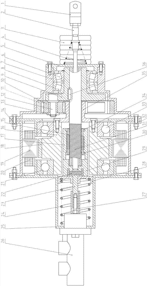
[0039] Such as figure 1 As shown, the present invention provides an integrated controlled-by-wire hydraulic brake device. The integrated controlled-by-wire hydraulic brake device is installed between the brake pedal and the brake master cylinder 26, and the brake master located at the front end It consists of a cylinder connection assembly, a motor assembly and a planetary roller screw mechanism at the middle and front end, a planetary gear mechanism at the middle and rear end, a brake pedal connection assembly at the rear end, and an end cover housing assembly.

[0040] The brake master cylinder connection assembly includes: rubber feedback disc 22, output push rod 23, return spring 24, master cylinder push rod 27, spring seat 28 and stroke adjustment base 29;

[0041] The m...


PUM


Abstract

The invention provides an integrated type drive-by-wire hydraulic braking device. The integrated type drive-by-wire hydraulic braking device is composed of a braking main cylinder connecting assembly, a braking pedal connecting assembly, a end cover shell body assembly, a motor assembly, a planetary rolling column lead screw mechanism and a planetary gear mechanism. The motor assembly is next to the braking main cylinder connecting assembly. The planetary gear mechanism is next to the braking pedal connecting assembly. The planetary rolling column lead screw mechanism is located in a central hole of motor rotor magnetic steel in the motor assembly. A sun wheel of the planetary gear mechanism is coaxially connected with the motor rotor magnetic steel. A planetary frame of the planetary gear mechanism is coaxially connected with a hollow lead screw of the planetary rolling column lead screw mechanism. When the motor assembly works, the motor rotor magnetic steel drives the sun wheel to rotate, the planetary frame is further driven to rotate, the hollow lead screw is driven by the planetary frame, and a planetary rolling column lead screw nut of the planetary rolling column lead screw mechanism is driven to output displacement towards a braking main cylinder through the braking main cylinder connecting assembly. By means of the integrated type drive-by-wire hydraulic braking device, the size of the braking device is reduced, the integration level is improved, and arranging on a whole vehicle is achieved conveniently.

Description

technical field [0001] The invention belongs to the technical field of automobile brake systems. More specifically, it relates to an integrated drive-by-wire hydraulic brake device. Background technique [0002] The braking system of a traditional car usually adopts a vacuum booster structure. Its principle is to use the vacuum negative pressure to increase the force applied by the driver on the pedal to achieve the boosting effect on the driver during the braking process. However, the vacuum booster structure also It has the following significant disadvantages: such as the large volume of the vacuum booster, low integration, complicated layout on the vehicle, high dependence on the engine, and poor reliability. Therefore, vacuum boosters are no longer used on most models at present. device structure. With the rapid development of today's automobile technology, people's demand for the braking performance of automobiles is gradually increasing, and the demand for high integ...

Claims


Application Information

Patent Timeline
Patent Type & Authority Applications(China)
IPC IPC(8): B60T13/68B60T13/66B60T13/74
CPCB60T13/662B60T13/686B60T13/745B60T13/746
Inventor 李静刘鹏石求军杨力鸣
Owner JILIN UNIV
Why Eureka
Try Eureka