Pulling-pressing shaft type monorail beam supporting seat

A finale, single-track technology, applied in the field of rail transit, can solve problems such as unfavorable anchor bolt fatigue life, contact stress fatigue pitting, anchor bolt fatigue damage, etc., to improve fatigue resistance safety, reduce friction, and reduce construction costs Effect

Pending Publication Date: 2017-12-08
CHENGDU XINTU TECH
View PDF12 Cites 3 Cited by
  • Summary
  • Abstract
  • Description
  • Claims
  • Application Information

AI Technical Summary

Problems solved by technology

Therefore, the structure of the straddle-type monorail hinge shaft cast steel support is more complicated than that of ordinary supports, but it also has some shortcomings, such as: 1. The contact surface of the hinge shaft of the movable support and the movable strip hole is a line contact, The height adjustment part of the lower anchor bolt is also ring-line contacting and bearing pressure, so the hinge shaft and hinge seat must be made of high-strength and hard materials. Under the fatigue load of the train passing through, contact stress fatigue pitting is prone to occur; 2. In order to resist the horizontal force and bending moment transmitted by the beam body, the hem of the hinged cast steel support is connected with the cover beam under the support by four anchor bolts. In order to meet the needs of line adjustment, a The anchor tube and the bottom and top of the anchor bolt also use spherical gaskets to adapt to the deflection of the anchor bar when adjusting the linearity. However, due to the effect of friction, the anchor bar is subjected to a certain bending moment in addition to the tensile force after adjusting the linearity. Therefore, in the actual working state of the anchor bolt, there is a state of combined bending and pulling, which is very unfavorable to the fatigue life of the anchor bolt. Therefore, the anchor bolt adopts a double-strength design. In the actual use process, there are also cases of fatigue damage of the anchor bolt. , it is very difficult to replace the anchor

Method used


Image

  • Pulling-pressing shaft type monorail beam supporting seat
  • Pulling-pressing shaft type monorail beam supporting seat
  • Pulling-pressing shaft type monorail beam supporting seat

Examples


Embodiment 1

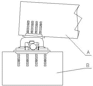
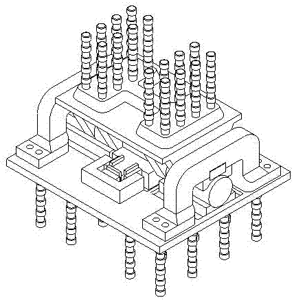
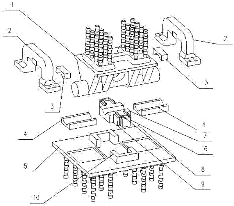
[0031] Such as figure 2 , 3 As shown, a tension and compression axis type monorail beam bearing includes an upper pendulum 1 and a lower bearing plate 4 .

[0032] On the support, a pendulum 1 such as Figure 4 , 5 As shown, it includes an upper top plate 1-1 and a horizontal cylinder fixedly arranged below it. The cylinder is divided into a positioning cylinder 1-6 in the middle and a rotating cylinder 1-7 coaxial with it at both ends. , the diameter of the positioning cylinder 1-6 is smaller than the diameter of the rotating cylinder 1-7 so as to form a stepped surface. The fixed connection between the cylindrical surface and the upper top plate 1-1 is realized through axial ribs 1-2 and radial ribs 1-3. A shear boss 1-8 is arranged on the top of the upper top plate 1-1. A reserved anchor hole 1-5 is opened in the middle of the axial rib 1-2 between the cylinder surface and the upper top plate 1-1. The rotating cylinder 1-7 protrudes from the upper top plate 1-1 cross...

Embodiment 2

[0038] A tension and compression axis type monorail beam support, comprising a support upper pendulum 1 and a lower support plate 4.

[0039] On the support, a pendulum 1 such as Figure 4 , 5 As shown, it includes an upper top plate 1-1 and a horizontal cylinder fixedly arranged below it. The cylinder is divided into a positioning cylinder 1-6 in the middle and a rotating cylinder 1-7 coaxial with it at both ends. , the diameter of the positioning cylinder 1-6 is smaller than the diameter of the rotating cylinder 1-7 so as to form a stepped surface. The fixed connection between the cylindrical surface and the upper top plate 1-1 is realized through axial ribs 1-2 and radial ribs 1-3. A shear boss 1-8 is arranged on the top of the upper top plate 1-1. A reserved anchor hole 1-5 is opened in the middle of the axial rib 1-2 between the cylinder surface and the upper top plate 1-1. The rotating cylinder 1-7 protrudes from the upper top plate 1-1 cross bridge to form a cantile...


PUM


Abstract

The invention discloses a pulling-pressing shaft type monorail beam supporting seat, which comprises a supporting seat upper pendulum and a lower supporting seat plate; the supporting seat upper pendulum comprises an upper top plate and column surfaces, in a transverse bridge direction, which are fixedly arranged on the lower side of the upper top plate; the column surfaces are divided into a middle positioning column surface and rotary column surfaces which are arranged on the two ends of the positioning column surface and are coaxially arranged with the positioning column surface; the diameter of the positioning column surface is smaller than that of each rotary column surface to form a step surface; the positioning column surface is embedded into a positioning groove, in the transverse bridge direction, of a cross-shaped positioning block; the two end parts, in a longitudinal bridge direction, of the positioning block are limited by positioning bosses; the rotary column surfaces extend out of two sides to form cantilever shafts; and the surfaces of the cantilever shafts are fixed on the lower supporting seat plate through portal frames respectively after being wrapped with an upper column panel and a lower column panel. According to the pulling-pressing shaft type monorail beam supporting seat, vertical load and drawing force load produced by tensioning are transferred by adopting a mode similar to contact between a shaft and the column surface, and a stress surface is large; matching among the cantilever shafts of the upper pendulum of the supporting seat, the upper column panel and the lower column panel can adapt to surface contact transfer of a beam rotation angle, a bending moment and a load; and an anchoring mode of the lower supporting seat plate and a cover beam is simple.

Description

technical field [0001] The invention relates to a beam support, in particular to a tension-compression shaft type monorail beam support, which belongs to the technical field of rail transportation. Background technique [0002] At present, the country is vigorously developing urban rail transit. Among them, the straddle monorail is a form that may be widely used in the future. At present, domestic straddle monorail is rarely used. Only Chongqing introduced Japanese technology around 2000 and established several straddle monorails. For seat-type monorail lines, the existing straddle-type monorail beam supports use hinged cast steel supports, which need to bear the vertical pressure, horizontal level, transverse bending moment, and plane bending moment transmitted by the vertical beam body. There are two modes of fixed and movable, and in order to adjust the linearity of the track, it is also required that the support can be adjusted horizontally and vertically before being fi...

Claims


Application Information

Patent Timeline
Patent Type & Authority Applications(China)
IPC IPC(8): E01B25/10
CPCE01B25/10
Inventor 邱廷琦夏玉龙刘海亮刘成杜传知王利君
Owner CHENGDU XINTU TECH
Why Eureka
Try Eureka