Automatic lubricant pump for hydraulic equipment

A technology of automatic lubrication and hydraulic equipment, applied in the direction of lubrication pump, engine lubrication, mechanical equipment, etc., can solve the problems of difficult layout, short service life of saw chains and guide plates, and high cost, and achieves convenient and simple installation, compact structure, and parts. less effect

Active Publication Date: 2017-12-08
广东鸿荣重工股份有限公司
View PDF9 Cites 2 Cited by
  • Summary
  • Abstract
  • Description
  • Claims
  • Application Information

AI Technical Summary

Problems solved by technology

[0002] The chain saw chain lubricating mechanism of the traditional large-scale hydraulic or mechanical logging machine is bulky, the transmission mechanism is complicated, the cost is high, and there is difficulty in adjusting the amount of lubricating oil, which cannot adapt to the automatic adjustment of the workload, resulting in waste of lubricating oil or poor lubrication effect The phenomenon
Or due to the difficulty of layout and high cost, the saw chain lubrication device is not installed. The above reasons cause the service life of the saw chain and guide plate to be short, and the saw chain and guide plate must be replaced frequently. At the same time, due to poor lubrication conditions, the sawing resistance will also increase. fuel consumption

Method used


Image

  • Automatic lubricant pump for hydraulic equipment
  • Automatic lubricant pump for hydraulic equipment
  • Automatic lubricant pump for hydraulic equipment

Examples


Embodiment Construction

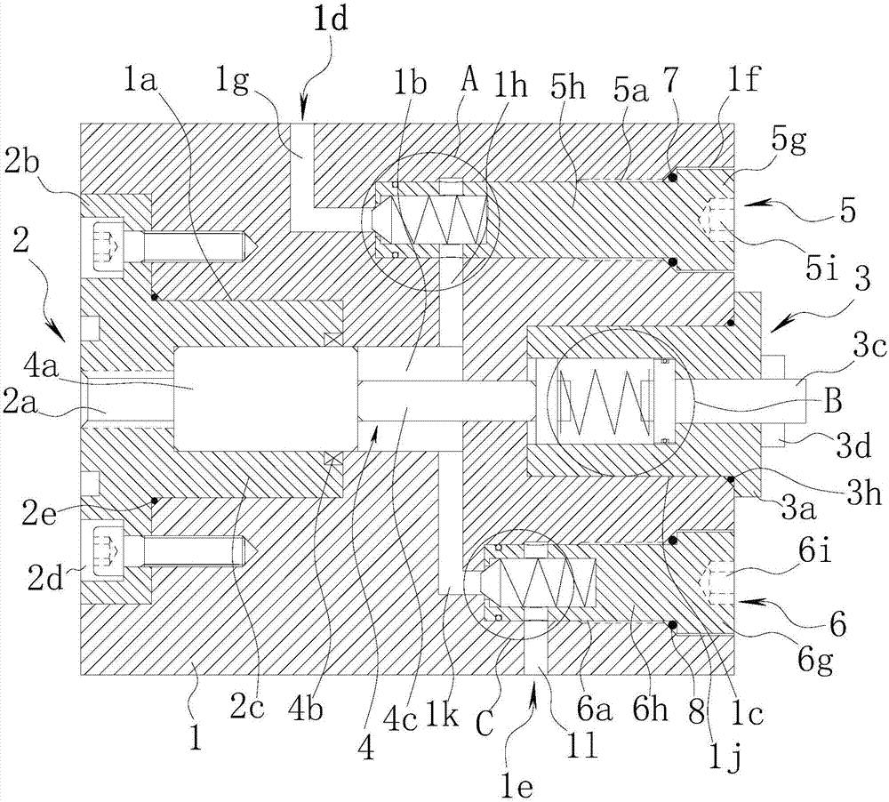
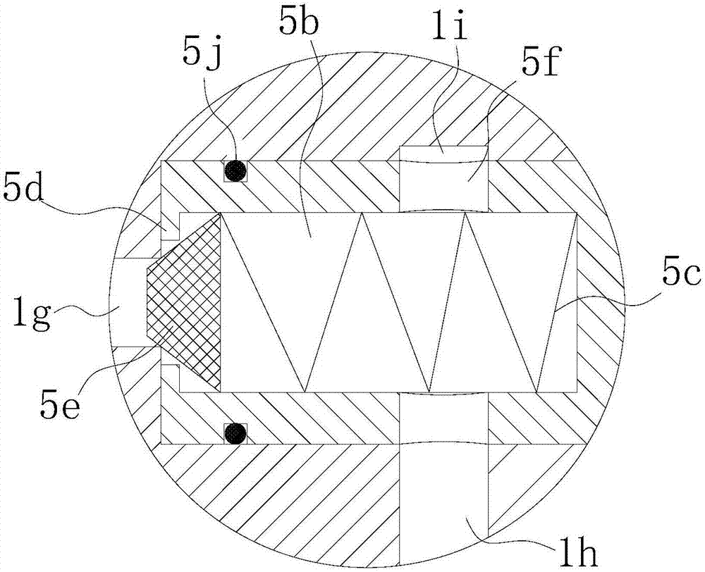
[0021] refer to Figure 1 to Figure 4 As shown, an automatic lubricating pump for hydraulic equipment according to the present invention includes a pump body 1, and the pump body is preferably cylindrical or square. One end surface of the pump body 1 is provided with a first installation groove 1a, a working chamber 1b is arranged at the inner bottom of the first installation groove 1a, and a cylinder body 2 is arranged in the first installation groove 1a.

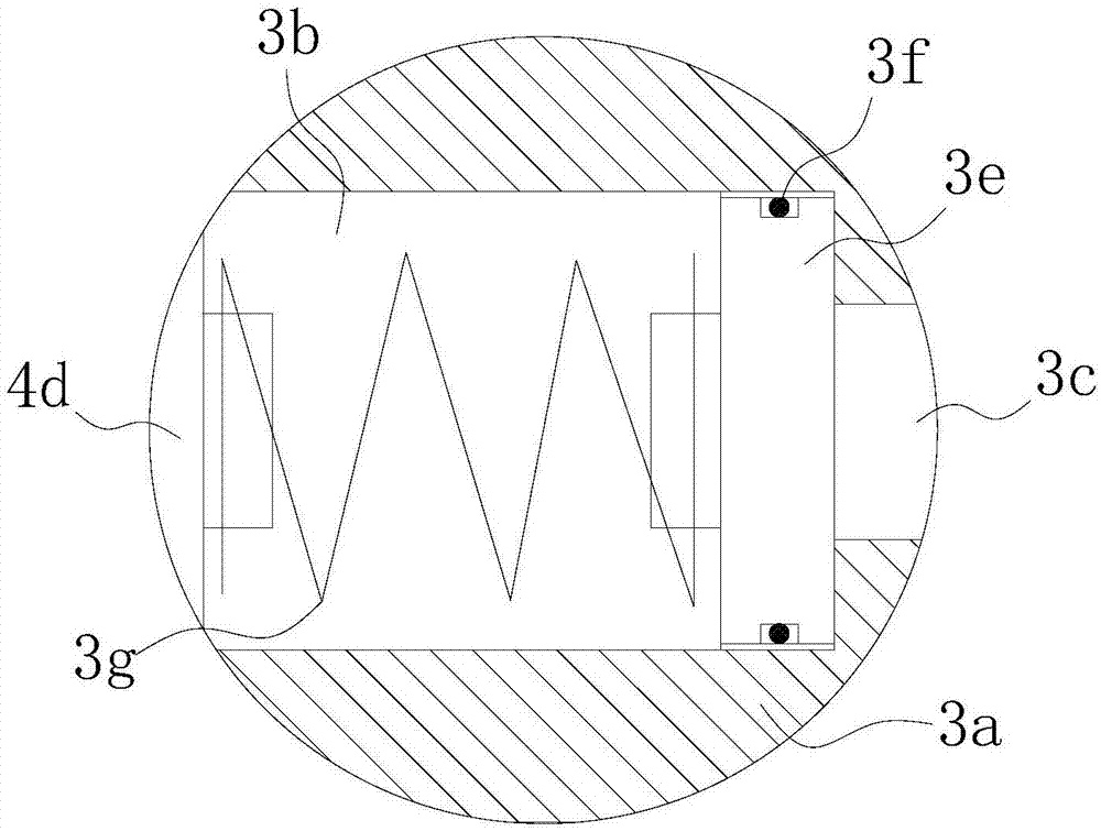
[0022] A second installation groove 1c opposite to the first installation groove 1a is provided on the other end surface of the pump body 1 opposite to the first installation groove 1a, and a pressure regulating mechanism 3 is arranged in the second installation groove 1c, and a pressure regulating mechanism 3 is arranged in the cylinder body 2 A pressure transmission mechanism 4 connected to the pressure adjustment mechanism 3 is provided inside, and an external pressure oil inlet 2a connected to the pressure transmission...


PUM


Abstract

The invention discloses an automatic lubricant pump for hydraulic equipment, belonging to the technical field of lubricant pumps. The automatic lubricant pump is characterized by comprising a pump body, a first installing groove is formed in one end face of the pump body, a working chamber is arranged at the bottom in the first installing groove, and a cylinder body is arranged in the first installing groove; a second installing groove, opposite to the first installing groove, is arranged in the other end face, opposite to the first installing groove, of the pump body, a pressure regulating mechanism is arranged in the second installing groove, a pressure conducting mechanism connected with the pressure regulating mechanism is arranged in the cylinder body, and an external pressure oil inlet communicated with the pressure conducting mechanism is arranged in the outer end face of the cylinder body; an oil inlet passage and an oil outlet passage are respectively arranged on the side walls of the working chamber, the oil inlet passage is connected with an automatic oil inlet valve, and the oil outlet passage is connected with an automatic oil outlet valve; the invention aims at providing the automatic lubricant pump for the hydraulic equipment, which is compact in structure and small and exquisite in size, can automatically adapt to the load conditions and has a good effect; the automatic lubricant pump is used for the lubrication for moving parts of the hydraulic equipment.

Description

technical field [0001] The invention relates to an auxiliary accessory of hydraulic equipment, more specifically, an automatic lubricating pump for hydraulic equipment. Background technique [0002] The chain saw chain lubricating mechanism of the traditional large-scale hydraulic or mechanical logging machine is bulky, the transmission mechanism is complicated, the cost is high, and there is difficulty in adjusting the amount of lubricating oil, which cannot adapt to the automatic adjustment of the workload, resulting in waste of lubricating oil or poor lubrication effect The phenomenon. Or due to the difficulty of layout and high cost, the saw chain lubrication device is not installed. The above reasons cause the service life of the saw chain and guide plate to be short, and the saw chain and guide plate must be replaced frequently. At the same time, due to poor lubrication conditions, the sawing resistance will also increase. fuel consumption. Contents of the invention...

Claims


Application Information

Patent Timeline
Patent Type & Authority Applications(China)
IPC IPC(8): F16N13/02
CPCF16N13/02
Inventor 吴柏强郭佳
Owner 广东鸿荣重工股份有限公司
Why Eureka
Try Eureka