
Cooking fume separating and purifying draught fan device

A purification fan and oil fume separation technology, which is applied in the field of kitchen utensil manufacturing, can solve problems such as energy consumption, cleaning difficulties, and inability to purify oil fume, and achieve sufficient contact time, good separation effect, and thorough oil fume separation.

Active Publication Date: 2017-12-08
FOSHAN NANFANG RITCO ENERGY CLEAN TECH CO LTD
View PDF16 Cites 3 Cited by
  • Summary
  • Abstract
  • Description
  • Claims
  • Application Information

AI Technical Summary

Problems solved by technology

[0003] Due to the large amount of oil vapor, water vapor and particulate matter in the oil fume, although the oil fume separation fans on the market can collect and process the oil fume generated on the kitchen stove to a certain extent, the treatment of the oil fume is not complete and cannot completely remove the oil fume. Purify, so that part of it will adhere to the filter screen and the inner wall of the pipe, so that it is necessary to manually clean the filter screen and the inner wall of the pipe frequently, but because the filter screen and the pipe are relatively concealed, it is difficult to clean; another part of the oil fume will enter To the electrostatic precipitator, it will cause frequent discharge of the electrostatic precipitator, consume energy and affect the service life of the high-voltage power supply for electrostatic precipitator

Method used


Image

  • Cooking fume separating and purifying draught fan device
  • Cooking fume separating and purifying draught fan device

Examples


Embodiment Construction

[0018] The idea, specific structure and technical effects of the present invention will be clearly and completely described below in conjunction with the embodiments and accompanying drawings, so as to fully understand the purpose, features and effects of the present invention. Apparently, the described embodiments are only some of the embodiments of the present invention, rather than all of them. Based on the embodiments of the present invention, other embodiments obtained by those skilled in the art without creative efforts belong to The protection scope of the present invention. In addition, all the connection / connection relationships mentioned in this article do not refer to the direct connection of components, but mean that a better connection structure can be formed by adding or reducing connection accessories according to specific implementation conditions. The various technical features in the invention can be combined interactively on the premise of not conflicting wi...


PUM


Abstract

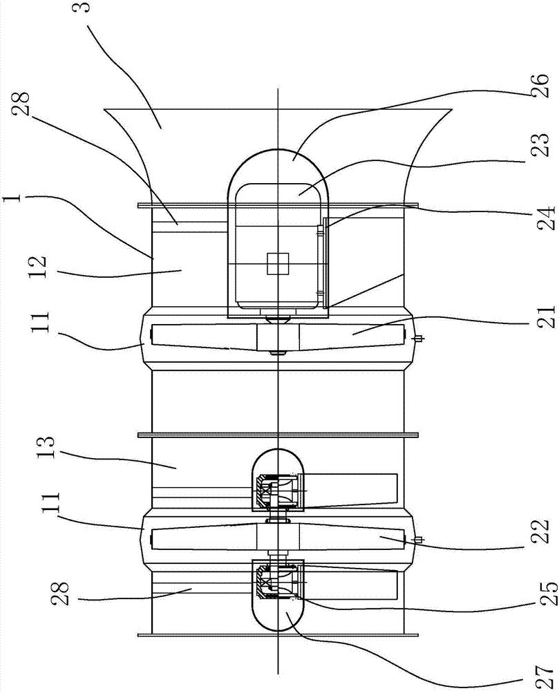
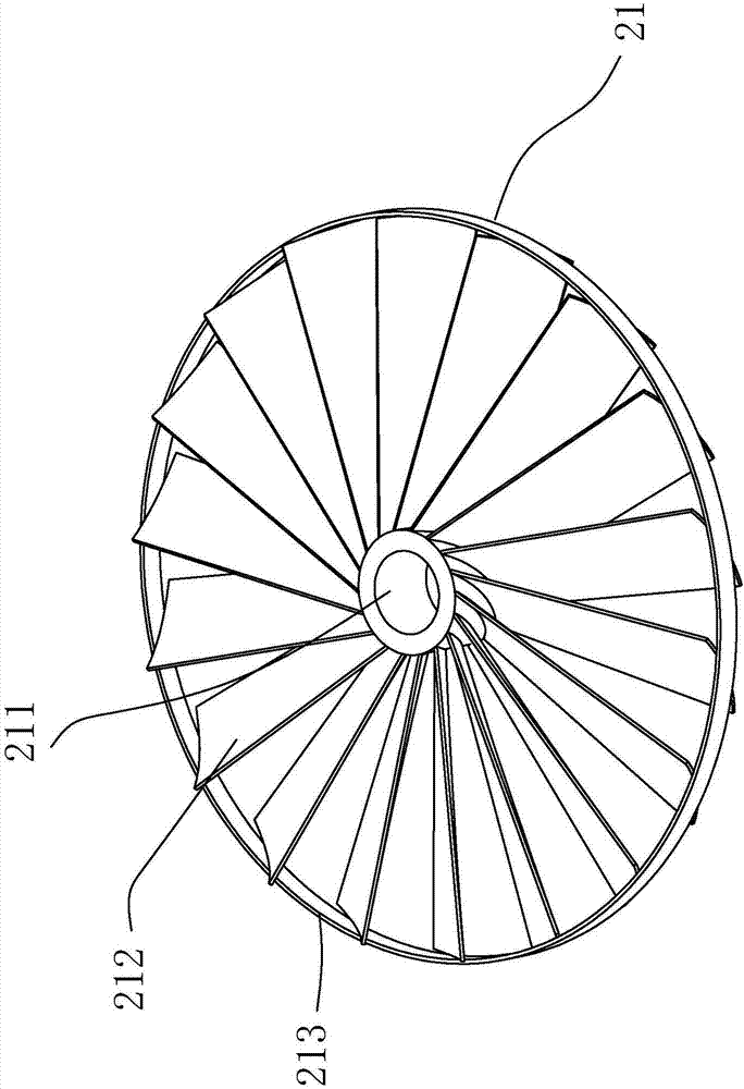
The invention discloses a cooking fume separating and purifying draught fan device. The cooking fume separating and purifying draught fan device comprises an air barrel. A draught fan is arranged in the air barrel and comprises a front separation impeller, a rear separation impeller and a motor. The motor is fixed to the middle of the air barrel through a supporting frame. The motor drives the front separation impeller to rotate, the rear separation impeller is connected with the air barrel through an installing base, the installing base is provided with a rotation shaft, and the rear separation impeller is connected with the rotation shaft. The axis of the rear separation impeller and the axis of the front separation impeller coincide with the axis of the air barrel. The rear separation impeller and the front separation impeller are in mirror symmetry. The two separation impellers on the same axis line are utilized, cooking fume is subjected to two-time cooking fume separation successively, and accordingly cooking fume separation is more thorough; meanwhile, the two separation impellers are driven only by one motor, one separation impeller actively rotates at a high speed, the other separation impeller passively rotates at a low speed, more sufficient contact time is provided for cooking fume and blades of the separation impellers, and accordingly the separation effect is better.

Description

technical field [0001] The invention relates to the technical field of kitchen utensil manufacturing, and more particularly relates to a blower device for separating and purifying oil fumes. Background technique [0002] The cooking fume produced not only causes environmental pollution, but also endangers human health. With the improvement of people's health awareness, lampblack pollution has become the focus of public attention. The existing oil fume treatment equipment mainly uses the oil fume separation fan to extract the oil fume, and then after simple filtration, it is finally purified by an electrostatic precipitator and then discharged into the atmosphere. [0003] Due to the large amount of oil vapor, water vapor and particulate matter in the oil fume, although the oil fume separation fans on the market can collect and process the oil fume generated on the kitchen stove to a certain extent, the treatment of the oil fume is not complete and cannot completely remove t...

Claims


Application Information

Patent Timeline
Patent Type & Authority Applications(China)
IPC IPC(8): F24C15/20
CPCF24C15/2035
Inventor 任刚崔兴华叶俊凯李环梁志杰董丽青
Owner FOSHAN NANFANG RITCO ENERGY CLEAN TECH CO LTD
Learn More