
Shell-and-tube heat exchanger

A shell-and-tube heat exchanger and heat exchange tube technology, applied in the direction of heat exchanger type, heat exchanger shell, indirect heat exchanger, etc., can solve the problems of poor thermal conductivity and poor heat exchange effect, and avoid overcooling. layer, ease of maintenance, effect of slowing down the flow

Inactive Publication Date: 2017-12-08
吴江华尔克斯机械设备有限公司
View PDF6 Cites 7 Cited by
  • Summary
  • Abstract
  • Description
  • Claims
  • Application Information

AI Technical Summary

Problems solved by technology

[0003] The technical problem to be solved by the present invention is to overcome that when the existing shell-and-tube heat exchanger is injected with the cooling medium from the shell side, a layer of heat conduction will be formed on the surface of the heat exchanger for a long time due to a large amount of cooling water flowing through the cooler. The subcooling layer with poor performance leads to the problem of poor heat transfer effect, and a shell-and-tube heat exchanger is provided

Method used


Image

  • Shell-and-tube heat exchanger
  • Shell-and-tube heat exchanger

Examples


Embodiment 1

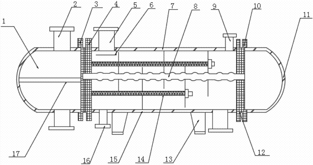
[0018] Such as Figure 1-2 As shown, the present invention provides a shell-and-tube heat exchanger, including a tube box 1 and a cylinder 7. The surface of the tube box 1 is provided with a tube-side connector 2 and a shell-side tube 5, and one side of the tube-side connector 2 The tube plate 4 is provided, the bottom of the shell-side connection tube 5 is provided with an anti-shock device 6, the inside of the cylinder 7 is provided with a corrugated heat exchange tube 8, and the surface of the cylinder 7 is provided with an exhaust port 9 and an exhaust port 9 One side is provided with a gasket 10, one side of the cylinder 7 is provided with a head 11, the bottom of the cylinder 7 is provided with a support 13, the bottom of the corrugated heat exchange tube 8 is provided with a tie rod 14, and the bottom of the tie rod 14 is provided with The baffle 15 is provided with a drainage port 16 on one side of the support 13, a partition plate 17 is provided inside the tube box 1, ...


PUM


Abstract

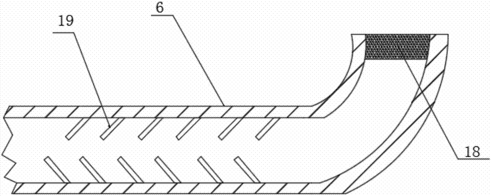
The invention discloses a shell-and-tube heat exchanger. The shell-and-tube heat exchanger comprises a tube body and a barrel body, wherein a tube pass connecting pipe and a shell pass connecting pipe are correspondingly arranged on the surface of the tube box; a tube plate is arranged at one side of the tube pass connecting pipe; a scour preventing device is arranged at the bottom part of the shell pass connecting pipe; a waved heat exchanging pipe is arranged in the barrel body, and an exhausting port is formed in the surface of the barrel body; one side of the exhausting port is provided with a spacer; a sealing head is arranged at one side of the barrel body, and a supporting seat is arranged at the bottom part of the barrel body; a pulling rod is arranged at the bottom part of the waved heat exchanging pipe, and a baffle plate is arranged at the bottom part of the pulling rod; a draining port is formed in one side of the supporting seat; a separating plate is arranged in the tube box; a filtering net is arranged on the top part of the scour preventing device, and a flowing limiting plate is arranged in the scour preventing device. With the adoption of the shell-and-tube heat exchanger, the problem that an undercooling layer with poor heat conducting performance is formed on the surface of the heat exchanger for a long term due to plenty of cooling water flows through a cooler when a pouring medium is poured into the shell-pass connecting pipe of an existing tube-and-shell heat exchanger, resulting in poor heat exchanging effect, can be solved.

Description

Technical field [0001] The invention relates to a heat exchanger, in particular to a shell-and-tube heat exchanger. Background technique [0002] Shell-and-tube heat exchanger is also called tube-and-tube heat exchanger. It is a partition type heat exchanger with the wall surface of the tube bundle enclosed in the shell as the heat transfer surface. This kind of heat exchanger has a simple structure and reliable operation. It can be made of various structural materials (mainly metal materials) and can be used under high temperature and high pressure. It is currently the most widely used type. The shell and tube heat exchanger is composed of shell, heat transfer tube bundle, tube sheet, baffle plate (baffle) and tube box. The shell is mostly cylindrical, with tube bundles inside, and both ends of the tube bundle are fixed on the tube plate. There are two kinds of fluids, cold and hot, which flow in the tube, called the tube side fluid; the other flows outside the tube, called t...

Claims


Application Information

Patent Timeline
Patent Type & Authority Applications(China)
IPC IPC(8): F28D7/08F28F9/22
CPCF28D7/08F28F9/22
Inventor 彭萍杨小梅包春燕李红领
Owner 吴江华尔克斯机械设备有限公司
Learn More