Rack-limiting and motor-driven driving simulation device steering device
A driving simulator and steering device technology, applied in the field of driving simulators, can solve the problems of large space occupation, high cost, small deformation, etc.
- Summary
- Abstract
- Description
- Claims
- Application Information
AI Technical Summary
Problems solved by technology
Method used
Image
Examples
specific Embodiment approach 1
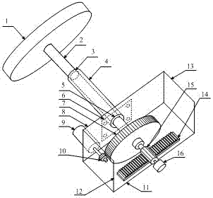
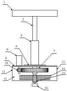
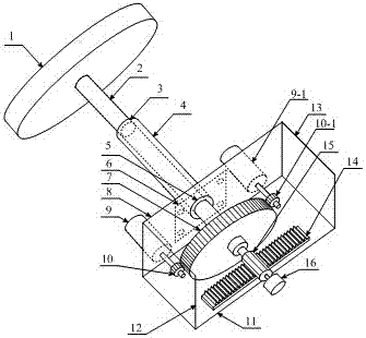
[0038] The invention provides a driving simulator steering device driven by a gear rack and a motor, such as figure 1 As shown, it is characterized in that it includes a steering wheel 1, a rotating shaft 2, a first bearing 3, a bearing sleeve 4, a second bearing 5, a bearing sleeve fixing plate 6, a first gear 7, and a steering gear Frame front plate 8, steering gear frame bottom plate 11, steering gear frame left side plate 12, steering gear frame right side plate 13, rack 14, third gear 15, angle measuring sensor 16, at least one set of motor 9 and motor 9 The matched second gear 10, the steering gear frame front plate 8, the steering gear frame bottom plate 11, the steering gear frame left side plate 12 and the steering gear frame right side plate 13 are used to form the steering gear frame body, and the ends of the bearing sleeves 4 are fixed The bearing sleeve fixing plate 6 is installed, and the bearing sleeve fixing plate 6 is fixedly installed on the front plate 8 of ...
specific Embodiment approach 2
[0045] This specific embodiment provides a driving simulator steering device with rack limit and motor drive, compared with specific embodiment 1, as Figure 5 As shown, it is characterized in that the angle measurement sensor specifically includes a circular magnet 16-5, a circuit board 16-3 and a Hall angle sensor 16-4, and the N pole and the S pole of the circular magnet 16-5 are in the On the same circular surface, the circular magnet 16-5 is glued to the end of the rotating shaft 2, and the circuit board 16-3 is non-contactly arranged on the outside of the circular magnet 16-5, and the circuit board 16-3 The Hall angle sensor 16-4 is arranged on the 16-3.
[0046] Compared with the first embodiment, the angle measurement sensor adopts a circular magnet, a circuit board and a Hall angle sensor. The magnetic field produced by the shaped magnet has a similar structure and characteristics, and the installation of the circular magnet is more convenient, but the manufacturing ...
specific Embodiment approach 3
[0047] This specific embodiment provides a driving simulator steering device with rack limit and motor drive, compared with specific embodiment 1, as Figure 6 As shown, it is characterized in that the angle measuring sensor adopts a potentiometer 16-6, and the end of the rotating shaft 2 is connected to the potentiometer 16-6.
[0048] Compared with Embodiment 1, the angle measurement sensor of this specific embodiment uses a potentiometer. Compared with the Hall angle sensor of Embodiment 1, the cost of the potentiometer is lower, but the service life of the potentiometer is shorter. Other technical effects are the same as those of the first embodiment, and will not be repeated here.
PUM
 Abstract
Description
Claims
Application Information
 - R&D
- Intellectual Property
- Life Sciences
- Materials
- Tech Scout
- Unparalleled Data Quality
- Higher Quality Content
- 60% Fewer Hallucinations
Browse by: Latest US Patents, China's latest patents, Technical Efficacy Thesaurus, Application Domain, Technology Topic, Popular Technical Reports.
© 2025 PatSnap. All rights reserved.Legal|Privacy policy|Modern Slavery Act Transparency Statement|Sitemap|About US| Contact US: help@patsnap.com


