Die-casting die and die-casting device

A die-casting mold and mold technology, applied in the field of die-casting molds and die-casting equipment, can solve the problems of uneven temperature distribution of slider core pulling, difficulty in workshop production, cracking of mold structure, etc., and it is easy to stabilize the production state and improve the service life. Effect

Inactive Publication Date: 2017-12-12
天津市发利汽车压铸件有限公司
View PDF13 Cites 1 Cited by
  • Summary
  • Abstract
  • Description
  • Claims
  • Application Information

AI Technical Summary

Problems solved by technology

[0005] In order to improve the deficiencies of the prior art, the purpose of the present invention is to provide a die-casting mold and die-casting equipment to solve the problems existing in the prior art by punching holes on the existing mold structure to make cooling water channels, and that stress concentration will be formed in the processing area. The more processing holes, the greater the impact on the material matrix, and the more prone to cracking the mold structure after processing, and because the inner bore size of the product is not processed, the mold size needs to be monitored very strictly, and the replacement of spare parts can hardly be guaranteed after replacement. Qualified castings are produced immediately, and generally need to be repaired again before they can be used, causing difficulties in the production of the workshop; and due to the distribution of the waterway, the temperature distribution of the slider core will be uneven.

Method used


Image

  • Die-casting die and die-casting device
  • Die-casting die and die-casting device
  • Die-casting die and die-casting device

Examples


Embodiment 1

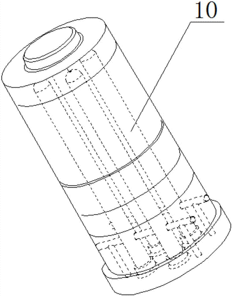
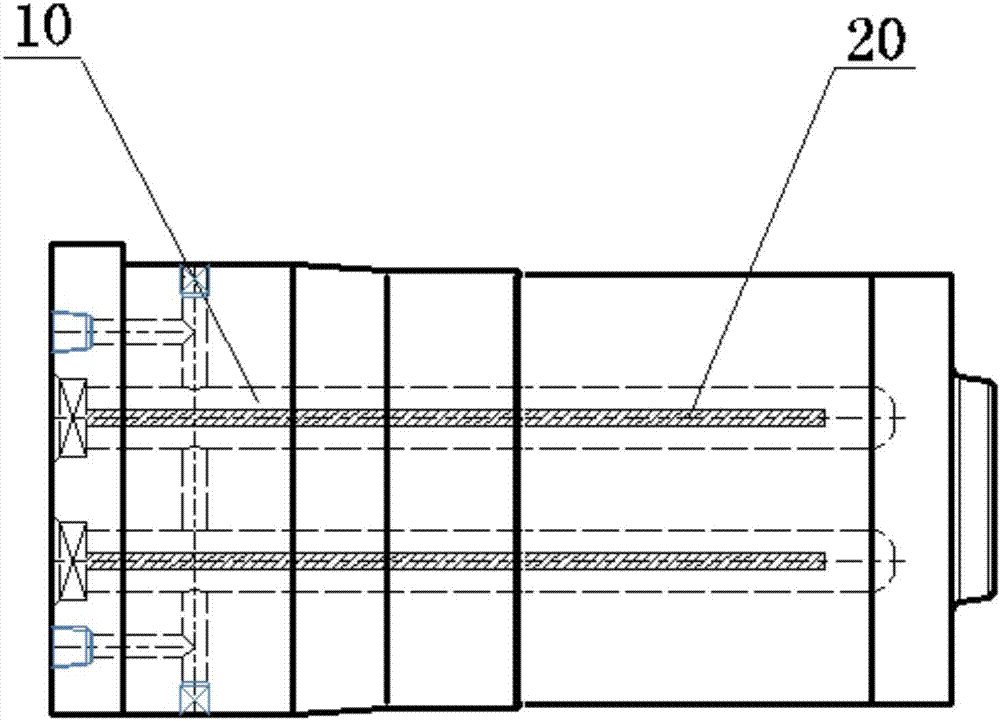
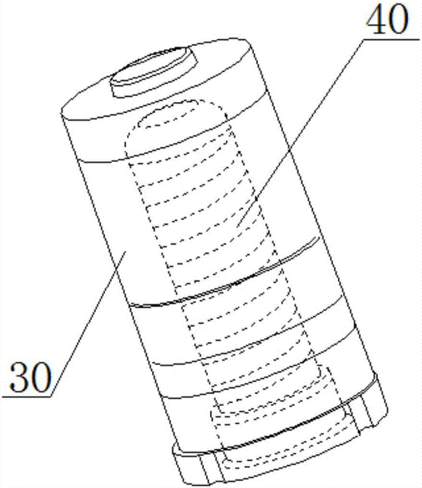
[0029] Such as figure 1 - Figure 6As shown, the die-casting mold provided by the present invention includes a mold core 30 and a cooling water circuit insert 40; the outer surface of the cooling water circuit insert 40 is provided with a helical structure, and the helical structure includes a spirally arranged groove; the The central position of the mold core 30 is provided with a blind hole 300, the blind hole 300 is used to install the cooling waterway insert 40, the inner wall of the blind hole 300 and the groove provided on the outer surface of the cooling waterway insert 40 form a spiral pipe 400; one end of the cooling water circuit insert 40 is provided with a water inlet 410 and a water outlet 420, and the water inlet 410 and the water outlet 420 communicate with the spiral pipe 400 to form a cooling water circulation loop. On the one hand, using the die-casting mold provided by the present invention can make the cooling water take away heat evenly from the mold core...

Embodiment 2

[0035] The die-casting mold provided by the present invention includes a mold core 30 and a cooling water circuit insert 40; a spiral structure is provided on the outer surface of the cooling water circuit insert 40, and the spiral structure includes a spirally arranged groove; the mold mold The central position of the core 30 is provided with a blind hole 300, the blind hole 300 is used to install the cooling water circuit insert 40, the inner wall of the blind hole 300 and the groove provided on the outer surface of the cooling water circuit insert 40 form a spiral pipe 400; One end of the cooling water circuit insert 40 is provided with a water inlet 410 and a water outlet 420, and the water inlet 410 and the water outlet 420 communicate with the spiral pipe 400 to form a cooling water circulation loop. On the one hand, using the die-casting mold provided by the present invention can make the cooling water take away heat evenly from the mold core 30, and form a uniform tempe...


PUM


Abstract

The invention relates to a die-casting die and a die-casting device. The die-casting die comprises a die core and a cooling water channel insert, a spiral structure is arranged on the outer surface of the cooling water channel insert and comprises a spiral groove, a blind hole is formed in the center of the die core and used for mounting the cooling water channel insert, the inner wall of the blind hole and the groove formed in the outer surface of the cooling water channel insert form a spiral pipeline, one end of the cooling water channel insert is provided with a water inlet and a water outlet, and the water inlet and the water outlet are communicated with the spiral pipeline to form a cooling water circulation loop.

Description

technical field [0001] The invention relates to the technical field of die-casting molds, in particular to a die-casting mold and die-casting equipment. Background technique [0002] In the existing motor shell products, the inner cavity of the molded motor shell needs to adopt a protruding cylindrical structure. Since it is a protruding structure, the setting of the cooling water circuit of this structure is very important. [0003] Such as figure 1 and figure 2 As shown, the cooling of the existing mold generally adopts the form of "water well", and the deep hole 10 is processed and cooperates with the water barrier 20 to form a circulating water channel. Therefore, there are two following problems in the cooling water path of the existing mold: one is to drill holes on the mold structure to make the cooling water path, and stress concentration will be formed in the processing area. The more holes are processed, the greater the impact on the matrix of the material, whic...

Claims


Application Information

Patent Timeline
Patent Type & Authority Applications(China)
IPC IPC(8): B22D17/22
CPCB22D17/22B22D17/2218
Inventor 王洪刘士涛郭增未
Owner 天津市发利汽车压铸件有限公司
Why Eureka
Try Eureka