Efficient full-automatic intelligent welding equipment and working method thereof

A fully automatic, welding equipment technology, applied in welding equipment, auxiliary welding equipment, welding/cutting auxiliary equipment, etc., can solve the problems of rough solder joints, affecting product production quality, increasing defective product rate, etc., to improve accuracy Effect

Active Publication Date: 2017-12-12
浩科机器人(苏州)有限公司
View PDF11 Cites 0 Cited by
  • Summary
  • Abstract
  • Description
  • Claims
  • Application Information

AI Technical Summary

Problems solved by technology

[0003] In the process of processing the current barrel body, due to its particular shape, most of them are manually welded. Due to the uncontrollability and variability of manual welding, each product is different, and once the m

Method used


Image

  • Efficient full-automatic intelligent welding equipment and working method thereof
  • Efficient full-automatic intelligent welding equipment and working method thereof
  • Efficient full-automatic intelligent welding equipment and working method thereof

Examples


Embodiment 1

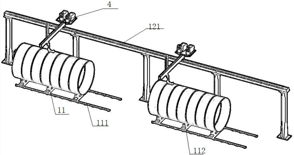
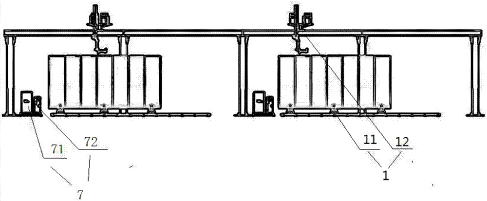
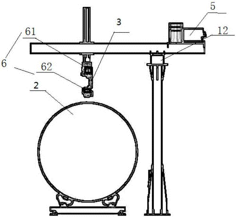
[0041] As shown in the figure, a working method of an efficient, fully automatic intelligent welding equipment, the efficient, fully automatic intelligent welding equipment includes: a fixing mechanism 1, a barrel body 2, a welding robot 3, a welding wire mechanism 4 for supplying welding wire, Welding power source 5, detection mechanism 6 and control device 7;

[0042] The relationship between the above components is as follows:

[0043] Wherein, the fixing mechanism 1 is provided with a barrel fixing mechanism 11 for fixing the barrel 2 and a robot fixing mechanism 12 for installing a welding robot, and the detection mechanism 6 is provided with a diameter detection mechanism for detecting the diameter of the barrel 2 instrument 61 and a position detector 62 for judging the welding position on the barrel body 2, the diameter detector 21 is arranged at one end of the barrel fixing mechanism 11, and the position detector 62 is arranged on the robot fixing mechanism 12;

[0044]...

Embodiment 2

[0054] As shown in the figure, a working method of an efficient, fully automatic intelligent welding equipment, the efficient, fully automatic intelligent welding equipment includes: a fixing mechanism 1, a barrel body 2, a welding robot 3, a welding wire mechanism 4 for supplying welding wire, Welding power source 5, detection mechanism 6 and control device 7;

[0055] The relationship between the above components is as follows:

[0056] Wherein, the fixing mechanism 1 is provided with a barrel fixing mechanism 11 for fixing the barrel 2 and a robot fixing mechanism 12 for installing a welding robot, and the detection mechanism 6 is provided with a diameter detection mechanism for detecting the diameter of the barrel 2 instrument 61 and a position detector 62 for judging the welding position on the barrel body 2, the diameter detector 21 is arranged at one end of the barrel fixing mechanism 11, and the position detector 62 is arranged on the robot fixing mechanism 12;

[005...


PUM


Abstract

The invention discloses a working method of efficient full-automatic intelligent welding equipment. The working method comprises the steps that a diameter detector is commanded to detect the diameter of a barrel through a diameter detection control unit in a controller module, the controller module drives supporting rollers through a supporting roller driving control module for internal adjustment, then a welding spot position detection control unit commands a position detector to start detecting a to-be-welded position on the barrel, a welding mechanism is driven to move to the to-be-welded position on the barrel through sliding connectors according to detected data, and the welding mechanism starts welding; a driving mechanism drives sliding rods to start moving to the next welding position so that welding can be continued; a turnover module commands a turnover mechanism to start rotating the barrel; and then the barrel is welded. The whole working process is simple, and through the diameter detector for detecting the diameter of the barrel and the position detector for judging the welding position on the barrel, the welding precision of a welding robot is greatly improved.

Description

technical field [0001] The invention belongs to the field of intelligent manufacturing, and in particular relates to a high-efficiency, fully automatic intelligent welding equipment and a working method thereof. Background technique [0002] With the rapid development of social economy, people's living standards and quality of life are constantly improving, and whether it is production or life, people's pace is constantly accelerating, and both people's production and life have achieved modernization and intelligence. The same is true for barrel welding. [0003] In the process of processing the current barrel body, due to its particular shape, most of them are manually welded. Due to the uncontrollability and variability of manual welding, each product is different, and once the manual welding is not skilled enough, Then it will cause the solder joints of its welding to be too rough, resulting in an increase in the rate of defective products, which seriously affects the pr...

Claims


Application Information

Patent Timeline
IPC IPC(8): B23K37/00B23K37/02B23K37/053
CPCB23K37/00B23K37/0252B23K37/053
Inventor 张家奇韩笑蕾周广平
Owner 浩科机器人(苏州)有限公司
Why Eureka
Try Eureka