Shot blasting machine roller way with shot leakage preventing device

A shot blasting machine and roller table technology, applied in the field of shot blasting machine roller table, can solve problems such as affecting the normal long work of the shot blasting machine, reducing the working efficiency of the shot blasting machine, affecting the normal operation of the equipment, etc., and achieves ingenious design and simple structure. , the effect of low cost

Pending Publication Date: 2017-12-12
江苏飞腾铸造机械有限公司
View PDF12 Cites 10 Cited by
  • Summary
  • Abstract
  • Description
  • Claims
  • Application Information

AI Technical Summary

Problems solved by technology

[0002] Due to the harsh working environment in the current market, a large number of projectiles leak through the gaps between the equipment during work, which will not only pollute the environment, affect the normal operation of the equipment, but even seriously affect the service life of the bearings, and a large number of projectiles splash out through the gaps. In the main body of the shot blasting machine, a large number of projectiles are wasted, resulting in increased production costs, affecting the normal work of the shot blasting machine, increasing the failure rate, and reducing the working efficiency of the shot blasting machine. This problem has become increasingly prominent

Method used


Image

  • Shot blasting machine roller way with shot leakage preventing device
  • Shot blasting machine roller way with shot leakage preventing device
  • Shot blasting machine roller way with shot leakage preventing device

Examples


Embodiment 1

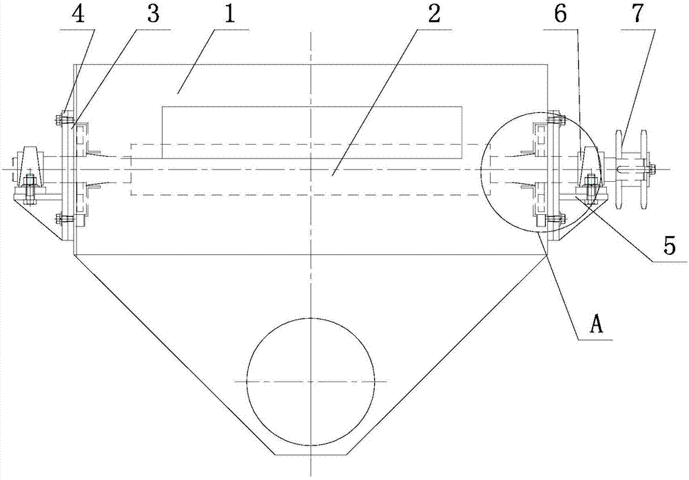
[0036] This embodiment provides a shot blasting machine roller table with an anti-shot leakage device, including a roller table 2 horizontally arranged in the main body of the shot blasting machine 1, and the two ends of the roller table 2 pass through the shot blasting machine respectively. The two side walls of the machine main body 1 protrude, and the central axis of the roller table 2 along its length direction coincides with the central axis of the shot blasting machine main body 1;

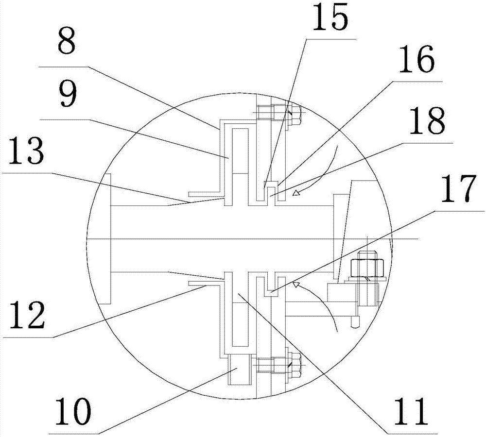
[0037] The shaft heads at both ends of the roller table 2 pass through the cover plates 3 arranged outside the two side walls of the main body of the shot blasting machine 1, and a bracket 4 is respectively provided on the outside of the cover plates 3 at both ends, and the shaft heads at both ends of the roller table 2 pass through On the back plate of the support 4, a platform 5 extends along the length direction of the roller table on the back plate of the support 4, and the cover plates 3...

Embodiment 2

[0050] This embodiment provides a shot blasting machine roller table with an anti-shot leakage device. The components of the metal coating are calculated in parts by mass: Ni: 8.5%, Ti: 10.5%, Si: 0.05%, Al: 0.25%, C: 0.03%, Mn: 2.17%, Na: 0.09%, Co: 0.28%, P: 0.003%, Cu: 0.55%, Zn: 0.27%, V: 0.28%, rare earth: 1.28%, the rest is Fe and unavoidable impurities;

[0051] The composite rare earth contains the following components by weight percentage: La: 15%, Dy: 2.5%, Pm: 0.28%, Eu: 1.5%, Nd: 5.5%; the rest is Ce and unavoidable impurities;

[0052] Wherein the preparation method of the wear-resistant metal coating is carried out according to the following steps:

[0053] Step (1): Send Ni, Ti, Si, Al, C, Mn, Na, Fe into the forging furnace for forging, the forging temperature is 1400°C, keep warm for 50min, then add Co, P, Cu, Zn, V elements, Increase the forging temperature to 1800°C, keep it warm for 60 minutes, then lower the temperature to 990°C, then add rare earth, kee...

Embodiment 3

[0059] This embodiment provides a shot blasting machine roller table with an anti-shot leakage device. The components of the metal coating are calculated in parts by mass: Ni: 8.3%, Ti: 10.4%, Si: 0.04%, Al: 0.24%, C: 0.02%, Mn: 2.16%, Na: 0.08%, Co: 0.25%, P: 0.002%, Cu: 0.54%, Zn: 0.26%, V: 0.26%, rare earth: 1.27%, the rest is Fe and unavoidable impurities;

[0060] The composite rare earth contains the following components by weight percentage: La: 13%, Dy: 2.4%, Pm: 0.27%, Eu: 1.4%, Nd: 5.3%; the rest is Ce and unavoidable impurities;

[0061] Wherein the preparation method of the wear-resistant metal coating is carried out according to the following steps:

[0062] Step (1): Send Ni, Ti, Si, Al, C, Mn, Na, Fe into the forging furnace for forging, the forging temperature is 1300°C, keep warm for 40min, then add Co, P, Cu, Zn, V elements, Increase the forging temperature to 1700°C, keep it warm for 50 minutes, then lower the temperature to 985°C, then add rare earth, kee...


PUM


Abstract

The invention discloses a shot blasting machine roller way with a shot leakage preventing device. The shot blasting machine roller way comprises a roller way horizontally arranged in a shot blasting machine body; shaft heads at two ends of the roller way respectively penetrate through two side walls of the shot blasting machine body to extend out; the axis of the length direction of the roller way is overlapped with the axis of the shot blasting machine body; bearings respectively sleeve the shaft heads at two ends of the roller way; bearing bases sleeve the bearings; the bearings on two sides and the bearing bases are totally identical, and are symmetrically arranged; a leakage preventing cover is arranged on the side wall in the shot blasting machine body, and sleeves the roller way; an annular cavity is formed in the leakage preventing cover; a discharge port is formed below the leakage preventing cover; the roller way is provided with an air blowing blade in the corresponding position of the annular cavity; an annular baffle plate outwards extends to one side of the leakage preventing cover; the roller way is provided with a conical table in the corresponding position of the annular baffle plate; and when the conical table approaches the leakage preventing cover, the outer diameter is gradually increased.

Description

technical field [0001] The invention relates to a roller table structure, in particular to a shot blasting machine roller table with an anti-shot leakage device. Background technique [0002] At present, due to the harsh working environment in the market, a large number of projectiles leak through the gaps between the equipment during work, which will not only pollute the environment, affect the normal operation of the equipment, but even seriously affect the service life of the bearings, and a large number of projectiles splash out through the gaps. In the main body of the shot blasting machine, a large number of projectiles are wasted, resulting in increased production costs, affecting the normal operation of the shot blasting machine, increasing the failure rate, and reducing the working efficiency of the shot blasting machine. This problem has become increasingly prominent. Contents of the invention [0003] In view of the shortcomings of the above-mentioned similar te...

Claims


Application Information

Patent Timeline
Patent Type & Authority Applications(China)
IPC IPC(8): B24C3/08B24C9/00C22C38/10C22C38/08C22C38/14C22C38/02C22C38/06C22C38/04C22C38/16C22C38/12C21D9/38
CPCC21D9/38C22C38/002C22C38/005C22C38/02C22C38/04C22C38/06C22C38/105C22C38/12C22C38/14C22C38/16B24C3/083B24C9/00
Inventor 潘绍兵
Owner 江苏飞腾铸造机械有限公司
Why Eureka
Try Eureka