Multifunctional cutting pliers

A kind of wire pliers and multi-functional technology, applied in the field of tools for maintenance of electric equipment tools, can solve the problems of inability to peel off the insulation layer of electric wires, damage to nuts, inconvenient replacement, etc., to increase practicability, effectively clamp, ensure safe effect

Inactive Publication Date: 2017-12-12
STATE GRID SHANDONG ELECTRIC POWER CO TAOXIAN POWER SUPPLY CO
View PDF13 Cites 4 Cited by
  • Summary
  • Abstract
  • Description
  • Claims
  • Application Information

AI Technical Summary

Problems solved by technology

[0003] Existing wire pliers have only one blade for cutting in the jaws, which can only be used for cutting, but cannot effectively strip the insulation layer of the wire, and often cause damage to the internal guide wire due to excessive force. It is necessary to use special wiring pliers; the jaws of the wire pliers are flat. Although the nut can be fixed to a certain extent, when the nut is removed, excessive force will cause damage to the nut and make subsequent removal more difficult. , so the wrench can only be replaced when disassembling the nut; when the workpiece needs to be clamped for a long time, only the maintenance personnel can hold it by hand, which greatly wastes manpower
These problems will appear in the same working environment. In order to solve these problems, carrying a variety of tools not only increases the load of the maintenance personnel, but also makes it inconvenient to change them during work. Therefore, how to change tools without frequent changes meeting multiple job demands becomes a pressing issue

Method used


Image

  • Multifunctional cutting pliers
  • Multifunctional cutting pliers
  • Multifunctional cutting pliers

Examples


Embodiment Construction

[0023] In order to better understand the present invention, the implementation manner of the present invention will be explained in detail below in conjunction with the accompanying drawings.

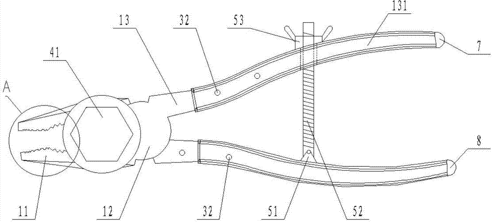
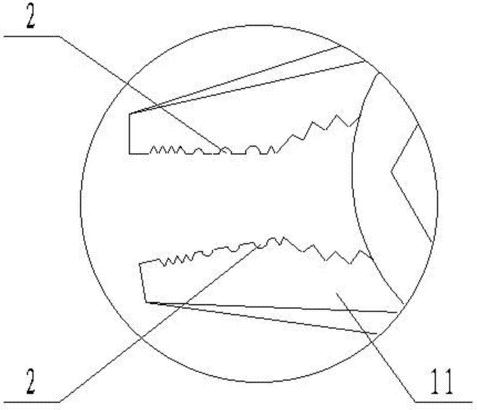
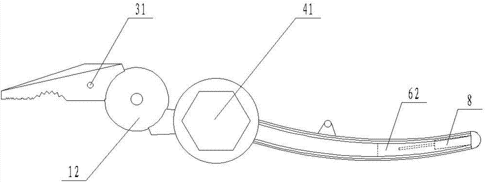
[0024] as attached figure 1 to attach Figure 5 As shown, it includes two oppositely arranged pliers bodies, stripping holes 2, nut fastening devices, clamping devices and auxiliary pliers handles 7, and each pliers body is successively pliers mouth 11, pliers gills 12 and pliers gills from left to right. The pliers handle 13, the two pliers bodies are hingedly connected at the pliers gills 12, several wire stripping holes 2 are sequentially arranged at the joints of the two pliers mouths 11, and the position near the edge is a blade, and the diameter of the circumference formed by the blade is the same as that of the inside of the wire. The diameters of the guide wires are equal. When you need to connect the wires, you only need to put the wires in the corresponding stripping holes 2 ...


PUM


Abstract

The invention discloses multifunctional cutting pliers. The multifunctional cutting pliers comprise two plier bodies which are oppositely arranged, wire stripping holes, a nut fastening device, a clamping device and an auxiliary handle bar. Each plier body is sequentially provided with a plier nozzle, a plier gill and a handle bar from left to right. The two plier bodies are hinged at the positions of the plier gills. The wire striping holes are formed in the butt joint position of the two plier nozzles. The right end of each plier nozzle is provided with a first limiting hole. The left end of each handle bar is provided with two second limiting holes. The nut fastening device comprises a nut sleeve and two vertical rods. The two vertical rods are welded to the bottom end of the nut sleeve and are further matched with the two first limiting holes or two second limiting holes. The clamping device comprises a hinged base, a bolt and a hold-down nut. The lower end of the bolt is hinged to the inner side of one handle bar through the hinged base, and the other handle bar is provided with a through hole corresponding to the bolt. The upper end of the bolt penetrates through the through hole and is further matched with the hold-down nut. The auxiliary handle bar is arranged at the right ends of the handle bars.

Description

technical field [0001] The invention relates to the technical field of tools for tool maintenance of electric equipment, in particular to a multifunctional wire cutter. Background technique [0002] As a common maintenance tool, wire cutters can not only clamp and fix the workpiece, but also bend and cut it. Now it has been widely used in various factories and enterprises, and has also been popularized in the field of daily life. [0003] Existing wire pliers have only one blade for cutting in the jaws, which can only be used for cutting, but cannot effectively strip the insulation layer of the wire, and often cause damage to the internal guide wire due to excessive force. It is necessary to use special wiring pliers; the jaws of the wire pliers are flat, although the nut can be fixed to a certain extent, but when the nut is removed, excessive force will cause damage to the nut and make subsequent removal more difficult. , so only a wrench can be used instead when disassemb...

Claims


Application Information

Patent Timeline
Patent Type & Authority Applications(China)
IPC IPC(8): B25B7/22H02G1/12
CPCB25B7/22H02G1/12
Inventor 王韶华牛劲松王悦张文秀孔晶王勇孙付美叶伟聂宝梅卢践为
Owner STATE GRID SHANDONG ELECTRIC POWER CO TAOXIAN POWER SUPPLY CO
Why Eureka
Try Eureka