
Automatic directed placing device for cylindrical crystal oscillators

A cylinder, crystal oscillator technology, applied in the direction of vibrating conveyors, conveyor objects, conveyors, etc., can solve problems such as affecting production efficiency, difficult to control the rotation angle of the placement direction, and difficult to control the placement direction of crystal oscillator pins, etc. Achieve the effect of fast movement, high precision and stable work

Pending Publication Date: 2017-12-12
淄博顺兴半导体有限公司
View PDF6 Cites 2 Cited by
  • Summary
  • Abstract
  • Description
  • Claims
  • Application Information

AI Technical Summary

Problems solved by technology

Because of the easy-to-tumble feature contained in the cylinder, it is difficult to control the placement direction and rotation angle of the cylinder when feeding
[0003] The cylindrical crystal oscillator is a typical cylindrical structure. When the cylindrical crystal oscillator is feeding materials, it is difficult to control the placement direction of the crystal oscillator pins. When using materials, it is necessary to correct the placement state of the materials under manual intervention. The process Seriously affect the production efficiency

Method used


Image

  • Automatic directed placing device for cylindrical crystal oscillators
  • Automatic directed placing device for cylindrical crystal oscillators
  • Automatic directed placing device for cylindrical crystal oscillators

Examples


Embodiment Construction

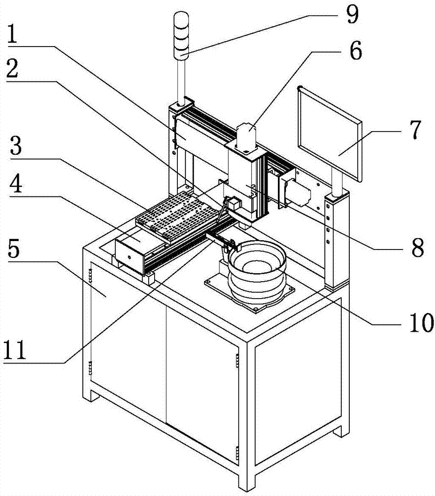
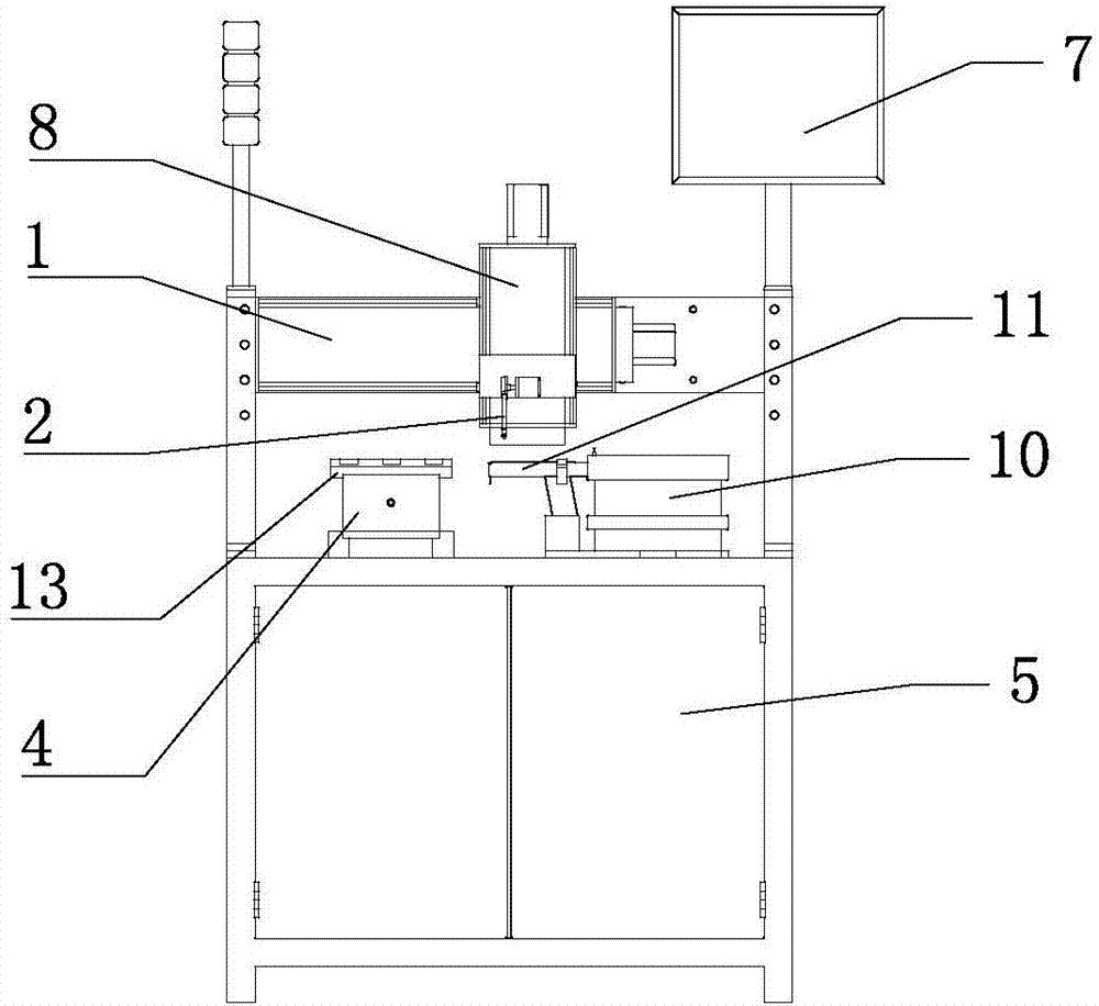
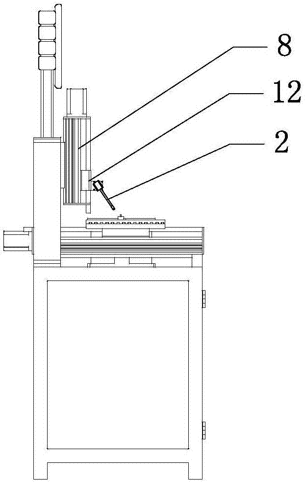
[0028] Such as Figure 1 to Figure 6 As shown, a cylindrical crystal oscillator automatic orientation placement equipment includes a frame 5, on which a feeding device and a crystal oscillator placement table are respectively provided, and a manipulator device is arranged between the feeding device and the crystal oscillator placement table. The manipulator device slides along the Y-axis track 1 on the upper part of the frame, the manipulator device is connected to the power device, and the power device uses a drive motor. A control device is provided on the frame 5, and the control device includes an upper computer 7, which is respectively connected with a feeding device, a crystal oscillator placement table, and a manipulator device. The frame 5 is also provided with a signal light tower 9.

[0029] Such as figure 1 , Figure 5 , Image 6 As shown, the feeding device includes a vibrating disk feeder 10 and a linear feeder 11, and the linear feeder 11 is connected to the unload...


PUM


Abstract

The invention relates to crystal oscillators machining and production equipment, in particular to an automatic directed placing device for cylindrical crystal oscillators. The automatic directed placing device for the cylindrical crystal oscillators comprises a rack. A feeding device and a crystal oscillator placing workbench are arranged on the rack. A manipulator device is arranged between the feeding device and the crystal oscillator placing workbench and slides along a Y-axis track on the upper portion of the rack. The automatic directed placing device for the cylindrical crystal oscillators can automatically feed the cylindrical crystal oscillators, the cylindrical crystal oscillators can be fed in a unified and constant posture in the feeding process, and subsequent procedures are conducted conveniently.

Description

Technical field [0001] The invention relates to crystal oscillator processing and production equipment, in particular to a cylindrical crystal oscillator automatic directional placement equipment. Background technique [0002] Differentiating and classifying cylindrical rollable objects according to their designated placement status is a difficulty in the current product feeding and discharging system. Because of the easy-to-roll feature contained in the cylinder, it is difficult to control the placement direction and rotation angle of the cylindrical object during feeding. [0003] Cylindrical crystal oscillator is a typical cylindrical structure. It is difficult to control the placement direction of the crystal oscillator pin when the cylindrical crystal oscillator is feeding. When using materials, manual intervention is required to correct the placement of the materials. The process Seriously affect the production efficiency. Summary of the invention [0004] In order to improv...

Claims


Application Information

Patent Timeline
IPC IPC(8): B65G27/02B65G47/91
CPCB65G27/02B65G47/91
Inventor 张海波于洪涛
Owner 淄博顺兴半导体有限公司
Learn More