Novel cable with explosive blast resistance

A new type of explosion shock technology, applied in the field of cables, can solve the problems of no cable body, anti-explosion protection, etc., and achieve the effect of attenuating shock waves and increasing the use time

Pending Publication Date: 2017-12-12
LIUZHOU OVM MASCH CO LTD
View PDF6 Cites 5 Cited by
  • Summary
  • Abstract
  • Description
  • Claims
  • Application Information

AI Technical Summary

Problems solved by technology

[0006] At present, the above-mentioned existing technical solutions are only for the anti-impact protection of the cable body, or the anti-blast protection technical solution for the anchorage area of ​​the bridge, but there is no anti-blast protection for the cable body

Method used


Image

  • Novel cable with explosive blast resistance
  • Novel cable with explosive blast resistance
  • Novel cable with explosive blast resistance

Examples


Embodiment 1

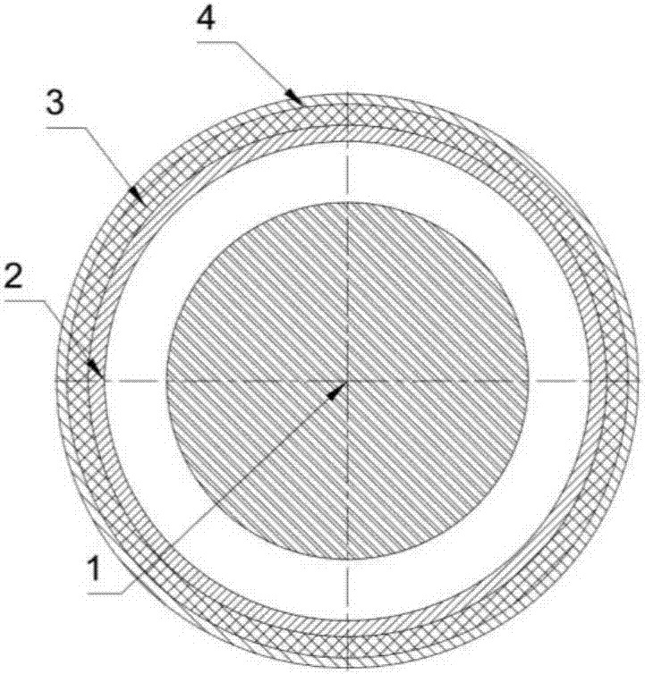
[0027] as attached figure 1 As shown, a novel anti-explosion shock cable, comprising a cable (1), a support tube (2) of a nested cable (1), is characterized in that the inner and outer walls of the support tube (2) are provided with anti-explosion Protective layer (3).

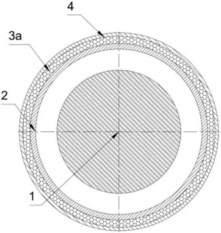
[0028] as attached figure 2 As shown, the support tube (2) is provided with an outer protection tube (4), and the gap between the support tube (2) and the outer protection tube (4) is filled with an anti-knock protection filling body (3a), and the anti-blast The protective filler (3a) is made of at least one of fiber reinforced concrete, active powder concrete, polyurea, polyurethane foam, aluminum foam, aluminum honeycomb or rubber. The outer protection tube (4) is nested outside the support tube (2), the anti-blast protection filling body (3a) is filled between the support tube (2) and the outer protection tube (4), and the cable (1) passing through the inside of the support pipe (2).

Embodiment 2

[0030] as attached figure 1 As shown, a novel anti-explosion shock cable, comprising a cable (1), a support tube (2) of a nested cable (1), is characterized in that the inner and outer walls of the support tube (2) are provided with anti-explosion Protective layer (3).

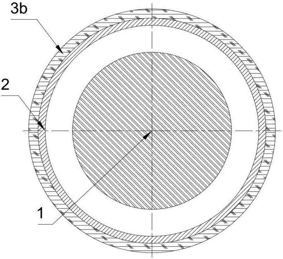
[0031] as attached image 3 , attached Figure 4 Shown, the anti-blast protective layer (3) of the inner and outer walls of the support pipe (2) is an anti-blast protective coating (3b), and the described anti-blast protective coating (3b) is a polyurea coating or a polyurethane coating. Made of at least one of . The outer wall of the support tube (2) is sprayed with an anti-knock protective coating (3b), and the cable (1) passes through the inside of the support tube (2); the inner wall of the support tube (2) is sprayed with an anti-knock protective coating layer (3b), the stay cable (1) passes through the inside of the support tube (2).

Embodiment 3

[0033] as attached figure 1 As shown, a novel anti-explosion shock cable, comprising a cable (1), a support tube (2) of a nested cable (1), is characterized in that the inner and outer walls of the support tube (2) are provided with anti-explosion Protective layer (3).

[0034] as attached Figure 5 As shown, the anti-blast protective layer (3) of the outer wall of the support tube (2) is an anti-blast protective cloth (3c), and the described anti-blast protective cloth (3c) is wrapped around the outside of the support tube (2). The protective cloth (3c) is made of at least one of fiber reinforced polymer, glass fiber cloth or carbon fiber cloth. The anti-blast protective cloth (3c) is wrapped around the outer surface of the support tube (2), and the stay cable (1) passes through the inside of the support tube (2).


PUM


Abstract

The invention discloses a novel cable with explosive blast resistance. The cable comprises a cable body (1) and a supporting tube (2) embedded with the cable body (1). The cable is characterized in that anti-explosion protective layers are arranged on the inner and outer walls of the supporting tube (2), and the supporting tube (2) can be sleeved with an outer protective tube (4) in an embedded mode. According to the cable, on the basis of unchanged original functions of the cable body, an anti-explosion structure is added to resist explosive blasts, and the cable has a multilayer structure for protection, so that damage on the cable caused by the direct explosive blasts is avoided.

Description

technical field [0001] The invention relates to a cable suitable for structures such as bridge engineering and construction engineering, in particular to a novel anti-explosion shock cable. Background technique [0002] As an important transportation infrastructure, bridges play a vital role in both military transportation and national economy. At present, terrorist activities are increasing worldwide, and bridge accidents caused by the threat of terrorist attacks and occasional explosions (such as the explosion of dangerous objects during vehicle operation) are increasing, which makes the anti-blast safety of bridge structures more and more concerned. At present, our country has not yet released the anti-blast protection design regulations for bridge structures, so it is necessary to carry out anti-blast protection design for bridge structures. [0003] The Chinese patent with the publication number CN205934724U discloses a kind of anti-collision steel strand cable-stayed ...

Claims


Application Information

Patent Timeline
Patent Type & Authority Applications(China)
IPC IPC(8): E01D19/16
CPCE01D19/16E04B2001/3583
Inventor 覃磊邹易清黄芳玮李文献雷欢庞锐剑张峰庞维林唐燕华庞贤剑石伟覃巍巍邱敏高宁妥韦耀淋
Owner LIUZHOU OVM MASCH CO LTD
Why Eureka
Try Eureka