
Pipeline type material sampling device

A sampling device and pipeline-type technology, which is applied in the field of pipeline-type material sampling devices, can solve the problems of sampling result deviation, complicated operation, and injury to sampling personnel, and achieve the effect of small external force and simple sampling operation

Inactive Publication Date: 2017-12-12
JIUJIANG TINCI ADVANCED MATERIALS CO LTD
View PDF6 Cites 0 Cited by
  • Summary
  • Abstract
  • Description
  • Claims
  • Application Information

AI Technical Summary

Problems solved by technology

However, there is currently no specialized sampling equipment, which leads to changes in the parameters of the PPM level during the sampling process due to various factors: the sampler itself reacts or dissolves with the material, causing deviations in the sampling results; some materials It will also react with moisture, oxygen, etc. in the air, which will eventually lead to unqualified sampling; and generally the sampling is close to the inner wall of the storage tank, and some materials may not be representative due to sedimentation and other reasons; some corrosive materials are sampled During the process, it is easy to cause injury to the sampling personnel; some samplers can meet some requirements, but the operation is complicated and not easy to operate
However, the sampler used in the laboratory is not suitable for use in chemical plants with relatively harsh environments. The problem of complicated sampling is a problem that many chemical plants are difficult to solve.

Method used


Image

  • Pipeline type material sampling device
  • Pipeline type material sampling device
  • Pipeline type material sampling device

Examples


Embodiment Construction

[0024] Below in conjunction with accompanying drawing and embodiment the present invention is further described:

[0025] see Figure 1-4 .

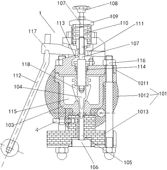
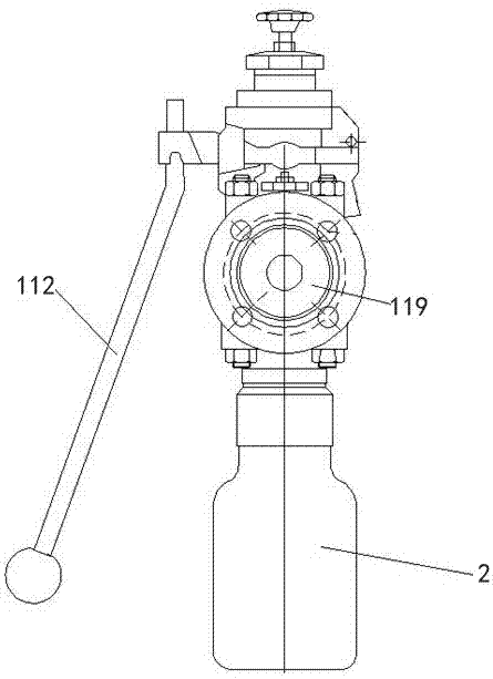
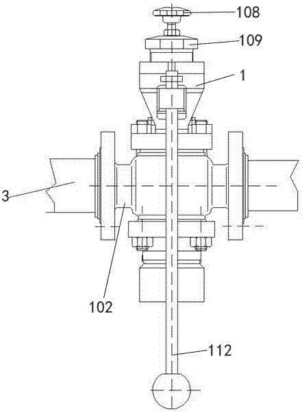
[0026] The invention discloses a pipeline type material sampling device, which comprises a sampling short connection device 1 and a sampling bottle 2 connected with a material delivery pipe 3, the main body of the sampling short connection device 1 is a tank body 101 with a cavity 115 , the front and rear sides of the tank body 101 are provided with through openings 102 for communicating with the material delivery pipe 3, the tank body 101 communicates with the material delivery pipe 3 through a flange 119, and the inside of the tank body 101 is provided with a valve seat 103 With the matching valve core 104, the bottom of the valve seat 103 is provided with a sampling channel 105, and the bottom of the sampling channel 105 is provided with a sampling port 106 for communicating with a sampling bottle, and the sampling channel 105 is nor...


PUM


Abstract

The invention relates to a pipeline type material sampling device. The pipeline type material sampling device comprises a sampling short-circuiting device and a sampling bottle which are communicated with a material conveying pipe, wherein a main body of the sampling short-circuiting device is a tank body with a cavity; penetrating openings are formed in the front side and the rear side of the tank body and are used for being communicated with the material conveying pipe; a valve seat and a valve core matched with the valve seat are arranged inside the tank body; a sampling channel is arranged at the bottom of the valve seat; a sampling opening communicated with the sampling bottle is formed in the lower part of the sampling channel; the sampling channel is in a normally-closed state; a valve rod is arranged above the valve core; a locking knob is arranged at the upper end of the valve rod; a top cover is also arranged outside the valve rod in a sleeving manner; a locking spring arranged outside the valve rod in the sleeving manner is arranged in the top cover and is in a compressed state; a pressure lever sleeve which is in fastening connection with the valve rod is arranged outside the valve rod in the sleeving manner; the pressure lever sleeve is connected with a handle positioned outside the tank body through a cross bar; and a rotating pivot is arranged at a position, located outside the valve rod, below the cross bar. The pipeline type material sampling device disclosed by the invention is uniform in sampling and has representativeness.

Description

technical field [0001] The invention relates to the field of chemical sampling, in particular to a pipeline type material sampling device. Background technique [0002] At present, in the chemical industry, it is necessary to take samples to test the quality of the products (materials) in various processes to judge whether they are qualified. However, there is currently no specialized sampling equipment, which leads to changes in the parameters of the PPM level during the sampling process due to various factors: the sampler itself reacts or dissolves with the material, causing deviations in the sampling results; some materials It will also react with moisture, oxygen, etc. in the air, which will eventually lead to unqualified sampling; and generally the sampling is close to the inner wall of the storage tank, and some materials will be unrepresentative due to sedimentation and other reasons; some corrosive materials are sampled During the process, it is easy to cause injury...

Claims


Application Information

Patent Timeline
Patent Type & Authority Applications(China)
IPC IPC(8): G01N1/20
CPCG01N1/2035G01N2001/205G01N2001/2071
Inventor 罗宇明杨进
Owner JIUJIANG TINCI ADVANCED MATERIALS CO LTD
Learn More